Table of Contents
Logic Module
- Nodes, Connectors and Connection new!
Each logic scheme represents a sheet containing block units. In the sheet it is possible to add several kinds of nodes, each one of them corresponding to a specific function in the server. The interaction of the node is defined by its connectors which are inputs and outputs of the node. Several nodes can be linked together by creating connections among the nodes. A connection is a link that starts from an output connector in a node and ends in an input connector.
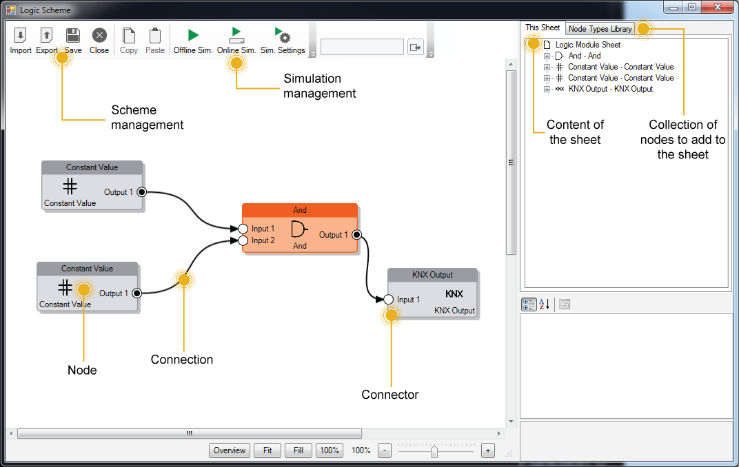
Scheme management
The logic scheme can be managed with the following buttons in the toolbar:
- Import It imports the block diagram contained in a XML file into the current logic scheme. This operation overwrites completely the logic scheme!
- Export It exports the current logic scheme in an XML file so that can be used inside other logic schemes. This operation doesn't save the current logic scheme inside the Configurator but just exports it!
- Save It saves the current logic scheme inside Configurator.
- Close It closes the logic scheme editor window.
Simulation management
The simulation feature allows to predict and debug what will happen when the block diagram will be executed inside the Thinknx server. Inside Thinknx Logic Module there are two kinds of simulation: Offline Simulation and Online Simulation.
Offline simulation simulates the behavior of the server by executing the block diagram inside Configurator and showing in realtime the values passing by all inputs and outputs of the nodes. In this way the user keeps trace of the values due some input values.
Online simulation connects to Thinknx server and provides feedback regarding the execution of the block diagram directly inside the server.Online simulation only works if the Configurator is in the same local network of the server. The IP needed for the connection corresponds to Local IP address specified in the System object.
The feedback provided while the simulation is running can be managed with some parameters by clicking the Sim. Settings button in the toolbar:
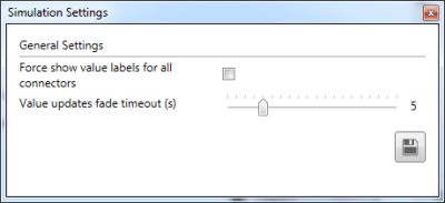
- Force show value labels for all connectors During a simulation, when the value passing by a connector is updated, a box showing the value appears beside the connector. To force this box to always be shown during simulation, check this box.
- Value updates fade timeout If the previous checkbox is unchecked, it indicates the time the update will be shown on the screen.
Nodes, Connectors and Connections
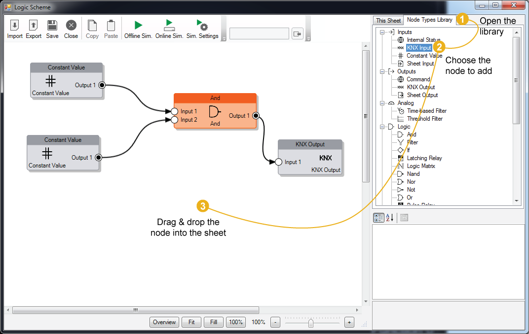
Create a node
To create a node, open the “Node Types Library” and drag the desired node into the sheet. For each node it is possible to edit its properties by clicking on it.
Edit a node
By selecting the node, the property grid gets populated with its properties, by editing them the behavior of the node will change.
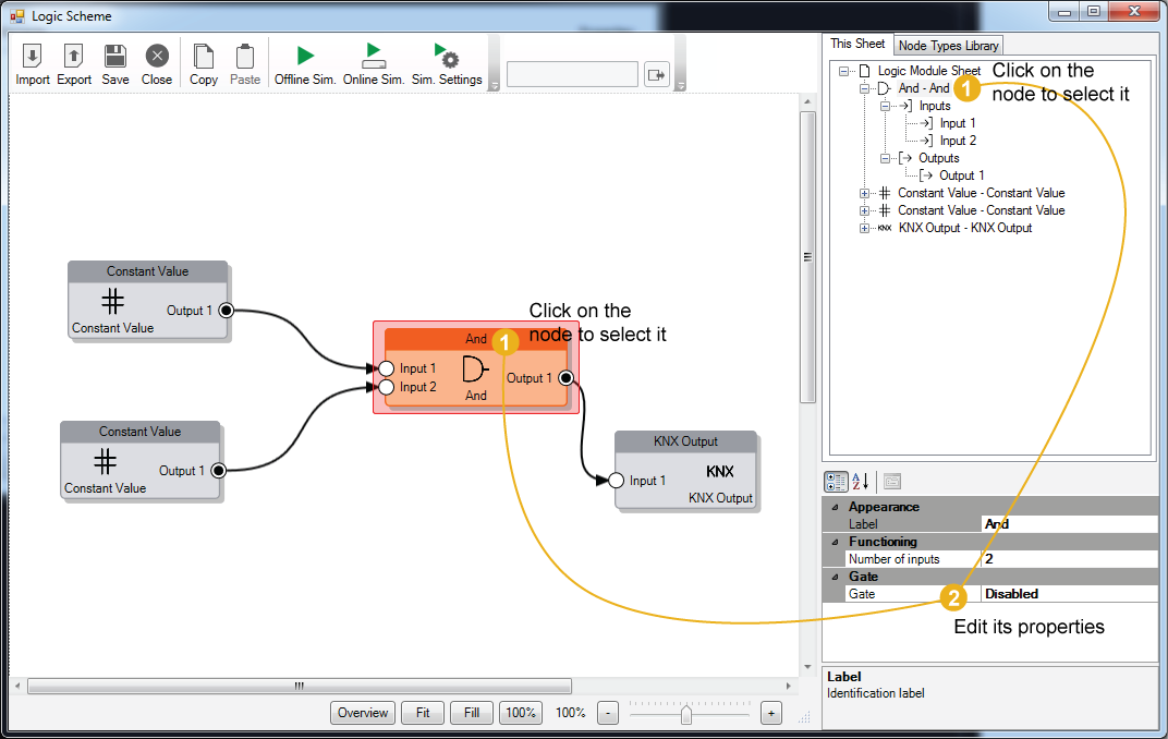
Every connector in the node has its own properties to describe its behavior. To edit them, click on the connector and the properties will be displayed in the property grid.
It is possible to select multiple nodes by pressing the Shift key.
Delete a node
To delete a node, select it and press Del key, or click on the little X icon which appears by moving the mouse over the node. After the node has been deleted, all the connection associated to the node will be removed.
Create a connection between nodes
To build the block diagram, it is necessary to link the nodes among each other. To create a connection click and hold one connector in the node and drag the mouse until the connector of the destination node. Before releasing the mouse, if the connection respects the standard rules among nodes, a green check will appear near the destination connector.
Connections can be established ONLY between an output connector and an input connector belonging to different nodes.
One output connector can link to several input connectors but one input connector can link to just one output connector!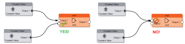
Data compatibility among nodes
There are no limitation in the creation of a new connection due to data compatibility, the incoming values will be automatically converted to the expected input type following these rules:
- Bit to Number When a logic output (a bit) is connected to an analog input (a number), the system will convert the logic 0 (False) to 0 and the logic 1 (True) to 1.
- Number to Bit When an analog output (a number) is connected to a logic input (a bit), the system will convert the analog value to a logic 0 (False) if it is equal to 0, and to a logic 1 (True) for all the other values.
- String to Bit When a string coming from an input node is connected to a logic input, the system will convert the string to a logic 1 (True) only if the string is equal to 1 or to “true”.
- String to Number When a string is connected to an analog input, the string value is converted into a number.
Gate connector
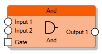
Except for input and output nodes, all the nodes can be enabled and disabled with the Gate connector. To show the Gate connector on the node, the Gate property on the node must be enabled.
When a node is disabled, the computation is not performed and no values are sent to the output connectors even if an input connector receives a new value.
By selecting the Gate connector it is possible to edit its properties which determine the behavior of the node:
- Inverted gate If disabled, the node is enabled when the connector's value is 1 and disabled when the connector's value is 0. By enabling this property, the behavior will be inverted (0 = node enabled, 1 = node disabled).
- Force output sending If enabled, when the node gets enabled, the values of all the output connectors are refreshed independently by the Output sending behaviour property of the corresponding output connector.
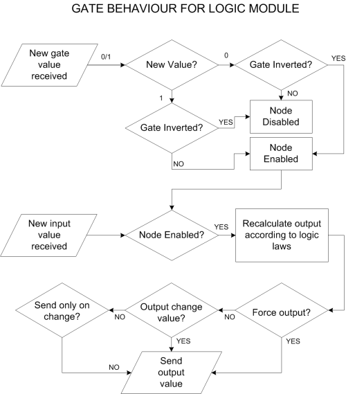
When the Gate property is enabled, if the Gate connector is not connected to any other node, the node is disabled by default. Otherwise, if the Gate connector is connected to a node but it is not receiving any value from the source of the connection, the node is still disabled.
The picture below describes the behaviour of the Gate in the node:
Await All Inputs
The “Await all inputs” property is available on each individual logic block (node) in the logic editor. When “Await all inputs” is set to True, the logic block will wait for all its inputs to receive a value before performing any calculation or producing an output. This ensures that the logic executes only when it has complete data from all its inputs.
Input nodes
The scheme should be able to read values coming from the plant as the the inputs of the block diagram or just provide some constants in the logic.
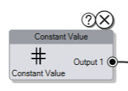
There are several kinds of Input nodes that can be used for this purpose:Output Connector
All the input nodes have only one output connector and the input value of these nodes will pass through it. In this connector it is possible to define the policy that will be used to forward the value to the connected nodes through the property:
- Output sending behavior It indicates when the value has to be forwarded to the connected nodes.
- ’On result change’ indicates that the result is sent only when different from the previous one.
- ’When a new input telegram is received’ indicates that the result is sent whenever the server receives a value update from the source of the input.
During Offline Simulation it is possible to simulate the value updates by manually typing them in the toolbar panel.
Output nodes
The scheme generates one or more output values to send on the KNX bus, commands to perform, etc. The output nodes represent the kind of action to perform with these values.
There are several kinds of Output nodes that can be used for this purpose:Input connectors
All the input connectors of output nodes have the following properties:
- Trigger Whenever a new value is received on the connector, if this property is enabled, the node triggers the “output action”.
Analog nodes
The Analog nodes represent a collection of node which perform analog operations.
Counter nodes
The Counter nodes, given an input (number or bit), perform a counting operation on the input and send it to the output.
There are several kinds of Counter nodes that can be used for this purpose:Output connectors
All the output connectors of the counter nodes have particular properties to manage the policies to send the values:
- Output sending behaviour The connector value will be updated depending on the following criteria:
- On new value reception Whenever the node updates the value, it sends it to the connector.
- After a fixed time interval The node sends the value to the connector at the expiration of a specified time interval, independently by the fact that the value has changed or not.
- On over-threshold change The node will compare the latest computed value with the previous one, if the difference between the two values overcrosses a predefined threshold it will send it to the connector. The threshold represents the ratio between the gap of the two values and the previously stored value.
- On over-threshold change and after time This option combines the advantages of both previously explained techniques. The node will send the value when over-threshold change occurs and, in any case, after a fixed time interval.
Store time interval Time interval to wait before the node sends the value to the connector.Change percentage Minimum change percentage required to send the value to the connector. To be sent, the new value has to differ from the previous value more than the percentage applied to the previous value.Logic nodes


