Table of Contents
Voip PBX & Doorcom

Every Thinknx server embeds a software VOIP telephony PBX. It is optimized for the VOIP functionalities between clients and for door communication. This object allows to configure the PBX (extensions, ring groups and door stations).
- PBX port This property allows to specify the PBX port if different from the default one (5060).
- Accounts PBX This property represents the list of extensions (clients) to be registered in the PBX.
- Ring groups This property represents the list of ring groups to be registered in the PBX. Ring groups allow to call more than one extension using a single number. The outdoor station can forward the call to several clients using a single number.
- Intercom devices This property represents the list of intercom devices to be registered in the PBX.
The diagram below gives a general overview on the configuration when using a Thinknx server as a VoIP PBX.

Thinknx server used as a VoIP PBX
When using an external VoIP PBX, there is no need to add the object “VoIP PBX” in System. All the extensions are configured on the external PBX. It is only essential to create one user per extension in “Sytem”–>“Users and Groups”, and disable the “System PBX” parameter in order to enter the correct settings for the user.
Adding PBX accounts
Click on the button displayed on the right to open the PBX users editor window, then click on ”Add” and adjust the properties in the grid:
- Extension This property allows to specify the extension number used by the client to join the PBX. Extension number starts from 100.
- Password This property allows to specify the password associated to the extension number.
Adding ring groups
Click on the button displayed on the right to open the ring groups editor window, then click on ”Add” and adjust the properties in the grid:
- Ring Group Number Number associated to this group in PBX. Group Numbers start from 9000
- Accounts PBX PBX accounts associated to this ring group
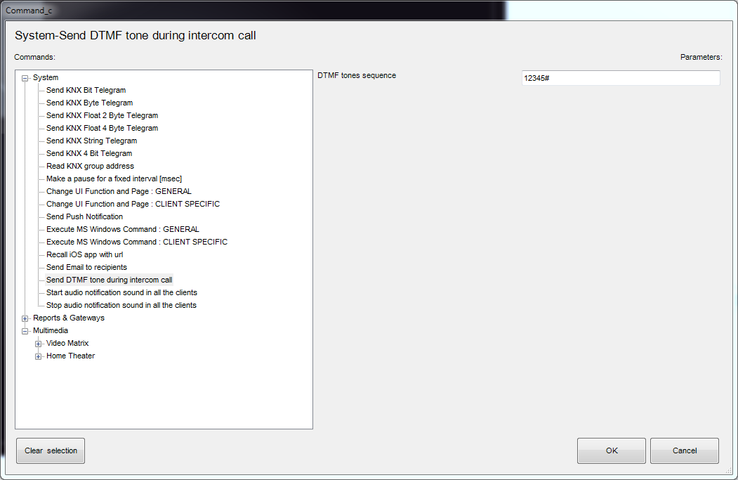
- Commands to execute Command to be executed in the event that this call group is called by another user. The command is executed when this call group receives the call.
Adding intercom devices
Click on the button displayed on the right to open the intercom devices editor, click on ”Add” and adjust the properties in the grid:
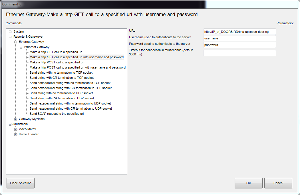
- Device type By selecting the option “Generic IP Doorstation” from the list, it is possible to integrate with most intercom support the SIP protocol such as:
- 2N
- Doorbird
- Fermax
- Mobotix
- TCS
- IpDoor
- and much more!
Username web This property corresponds to on of the login parameters of intercom management web page.Password web This property corresponds to on of the login parameters of intercom management web page.Username PBX This property corresponds to the extension used by the intercom to register in the PBX; it is automatically generated and it cannot be edited. For devices the numeration starts from 901.IP address Outdoor station address.Port Outdoor station port.Intercom buttons This property allows to configure the intercom button panel, associating to each button the extension or ring group to be called. Click on the button displayed on the right to open the intercom buttons editor, click on ”Add” and adjust the properties in the grid:- Label: Label associated to the button in the configurator.
- Button number: This property represents the button number on the panel.
- Call single user: If enabled, the call is sent to a single user when the button is pressed. If disabled, the call is sent to a ring group.
- Ring Group PBX: Ring group associated to this button.
User Interface
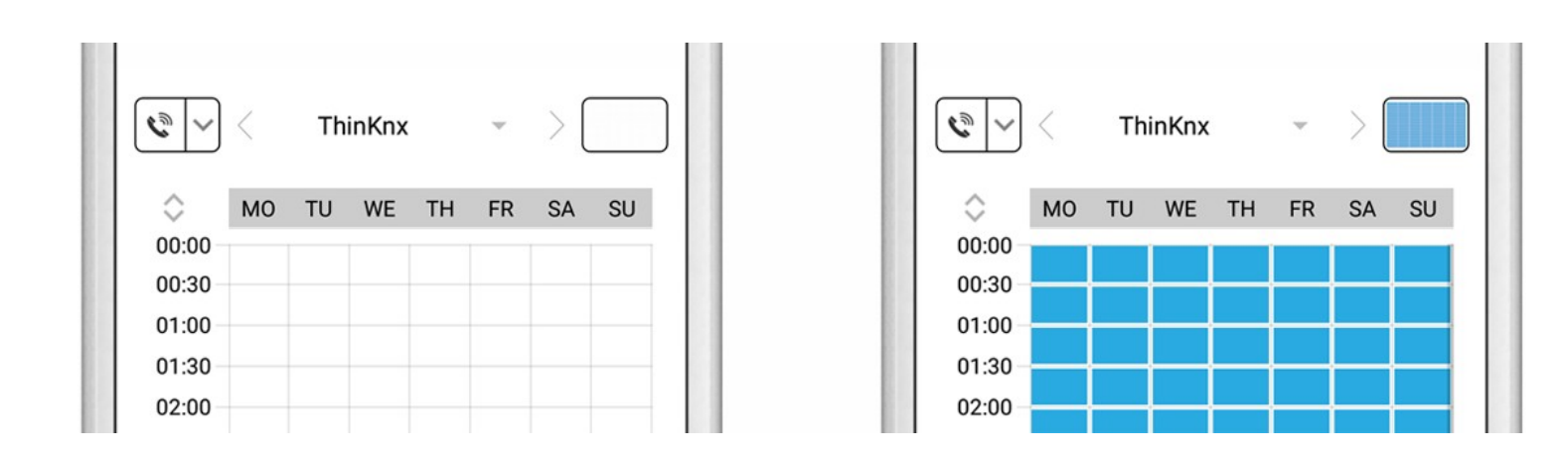
Enabling the SIP clients for users will make a handset appear at the top right of the client screen. The color of the handset will indicate different meanings:
- Red Handset - The connection to the server encountered an error. Check if the Client association was performed correctly.
- Yellow Handset - Client connection problems to the server. Check server logs and ensure client registration to PBX.
- White Handset - Connection successfully established.

Handset
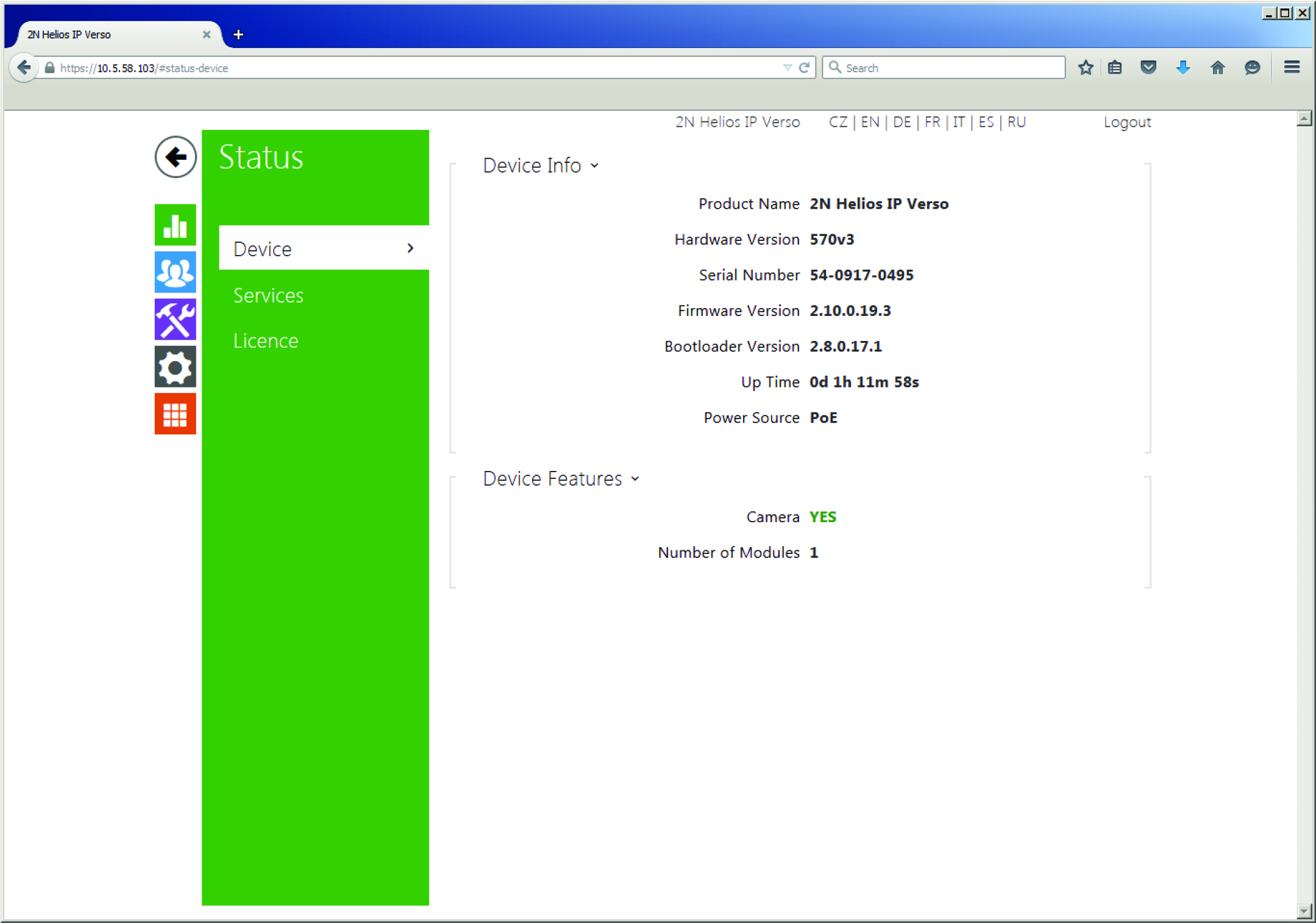
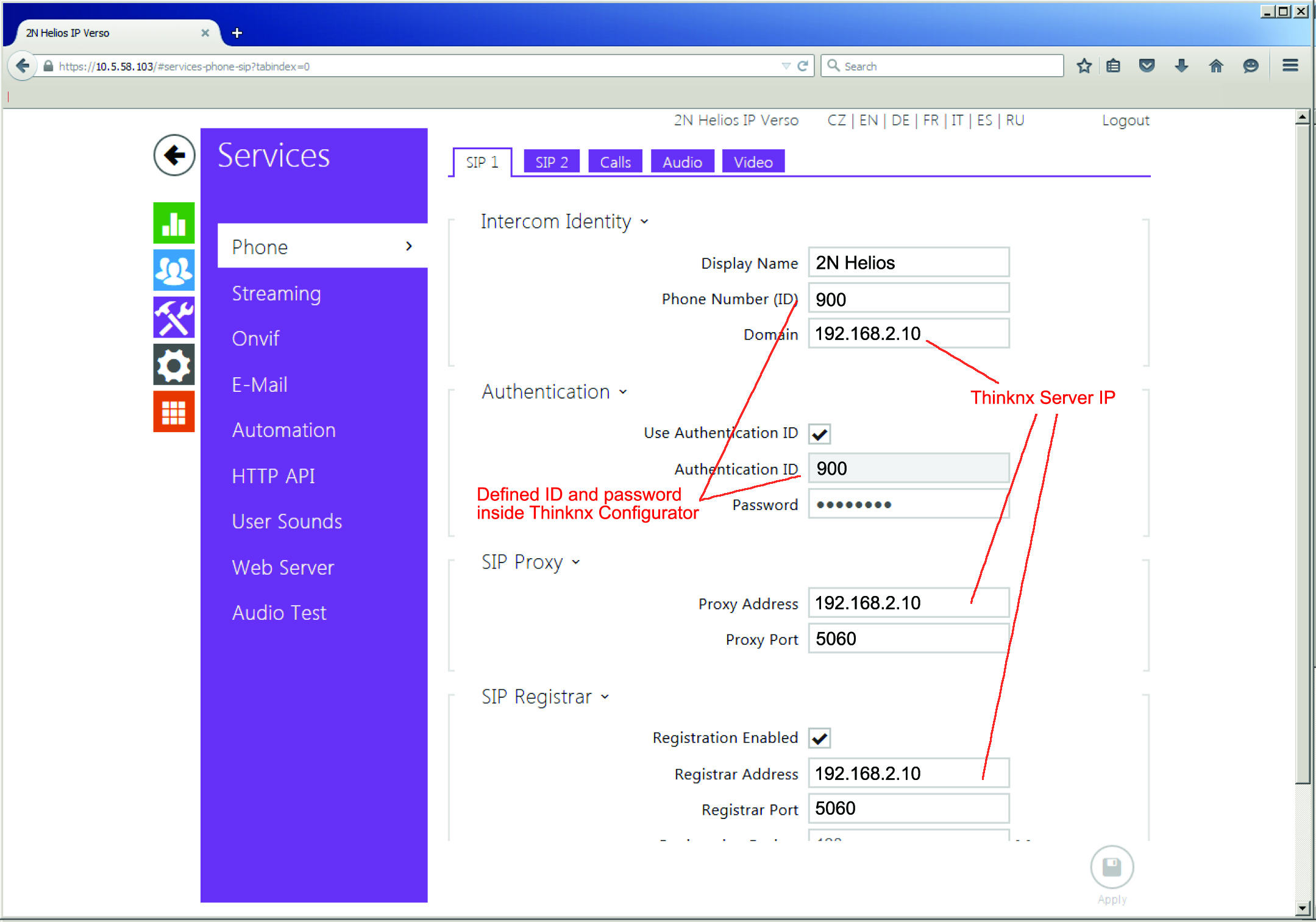
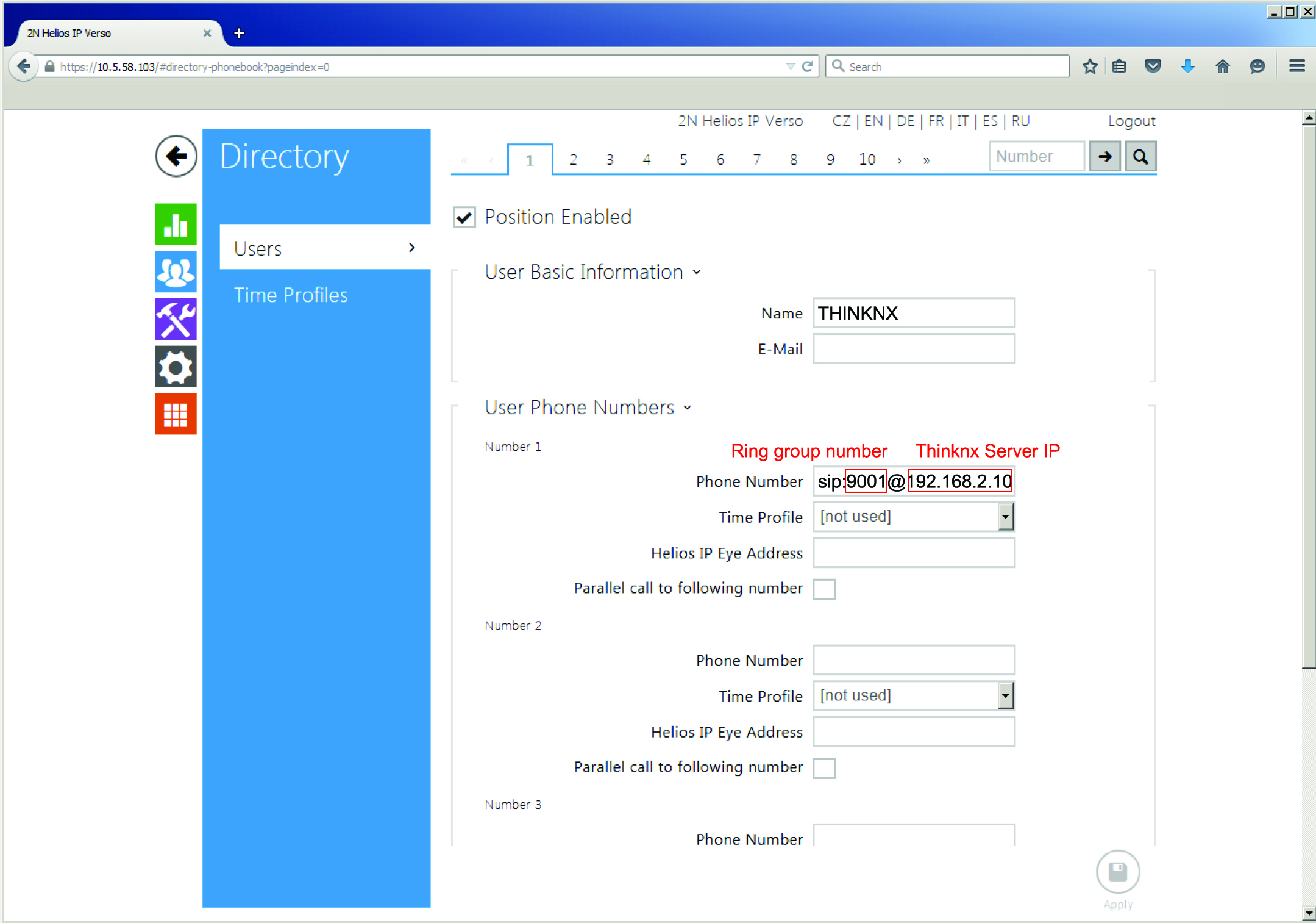
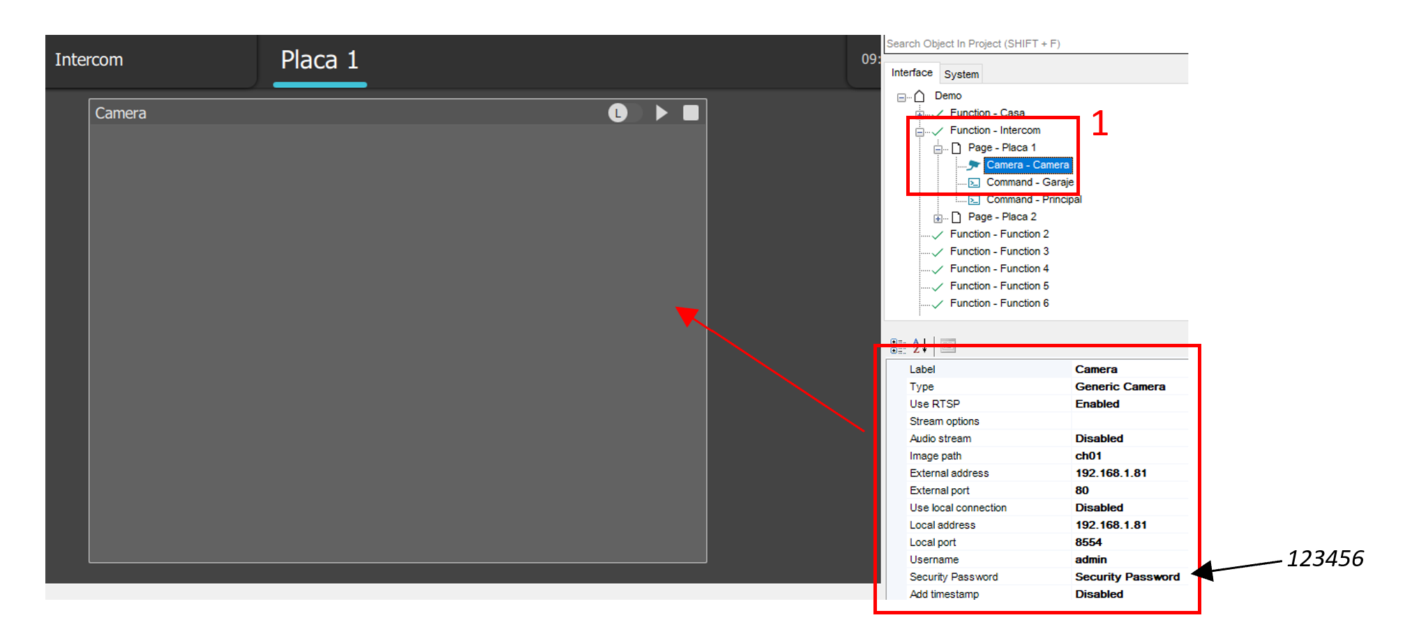
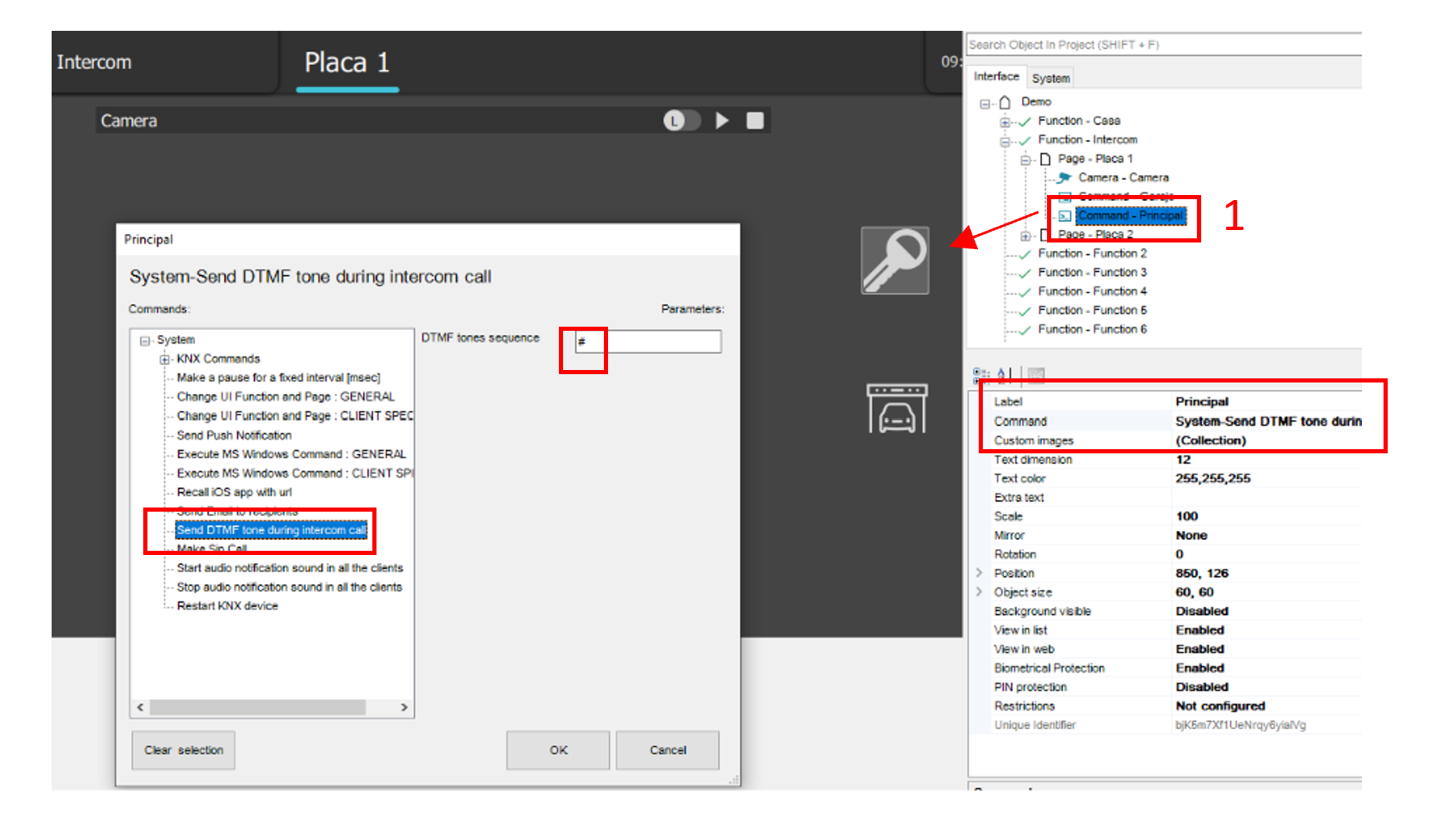
Integration example: 2N IP
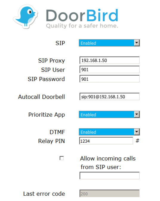
Integration example: Doorbird D10x, D20x
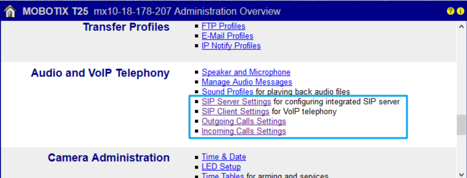
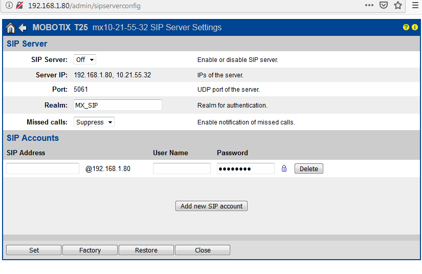
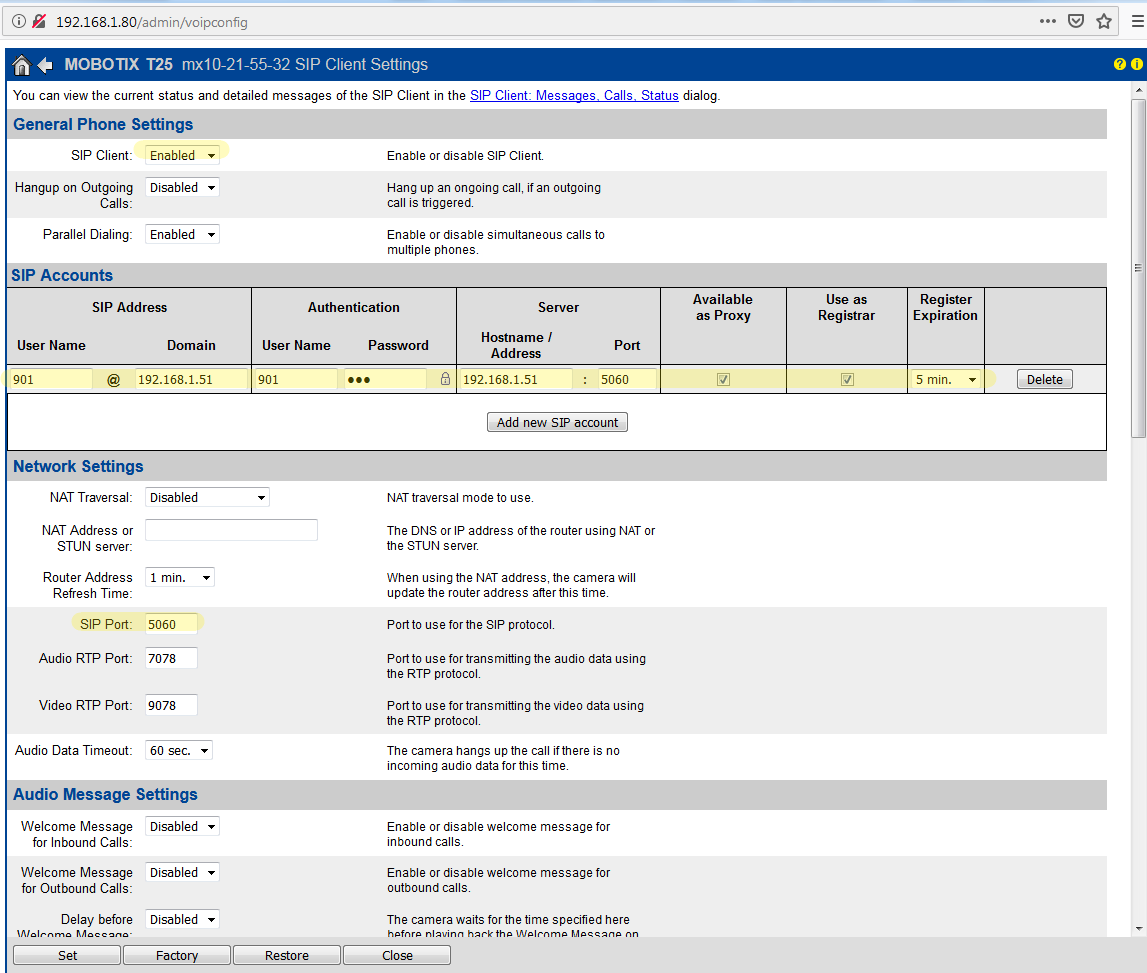
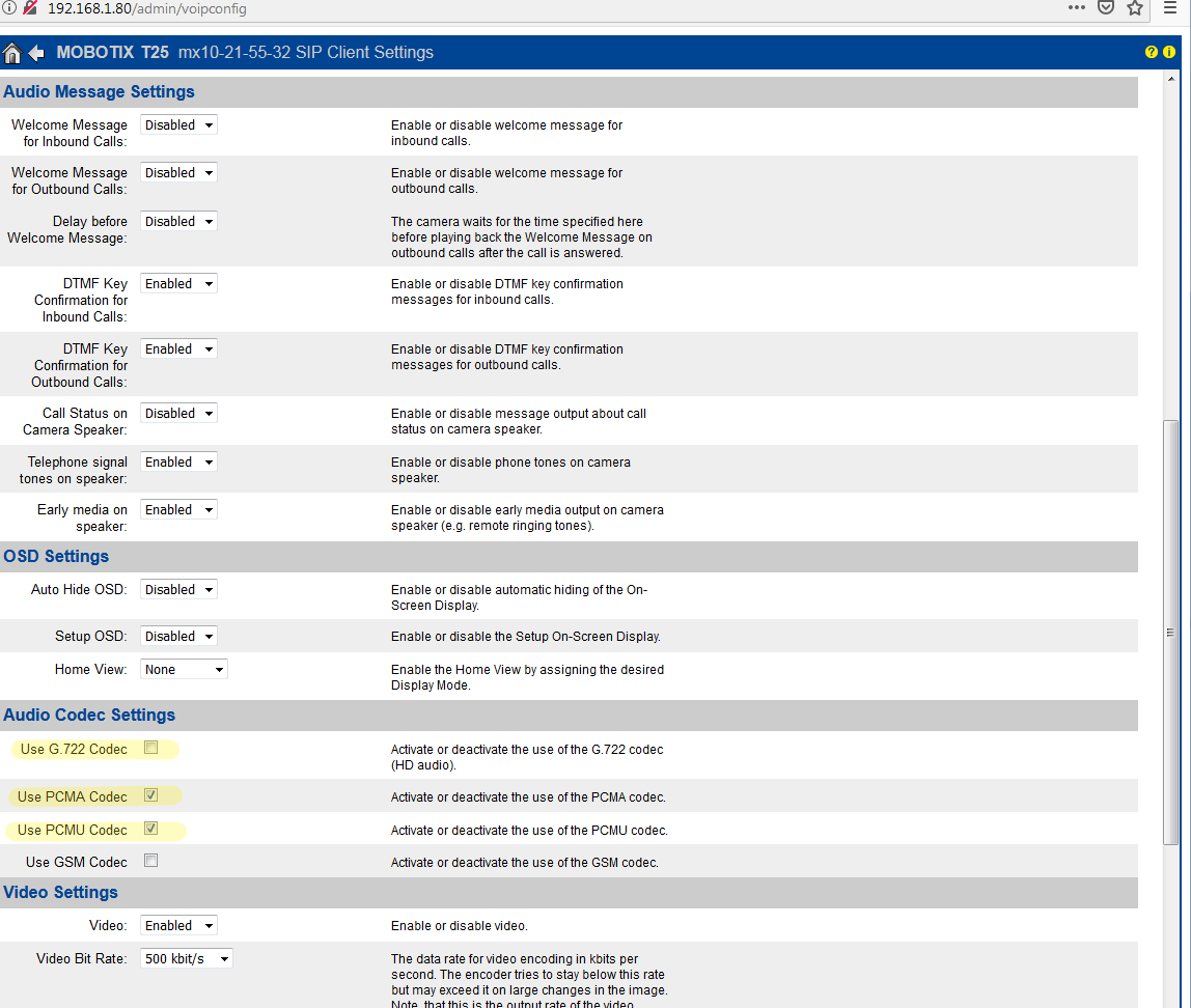
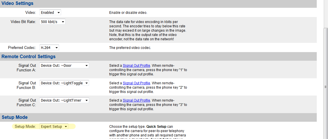
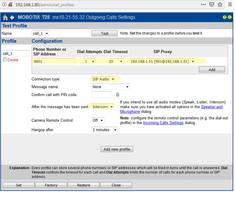
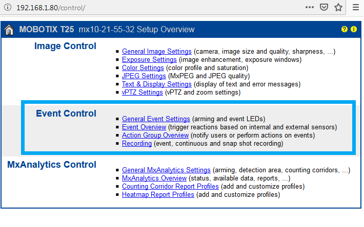
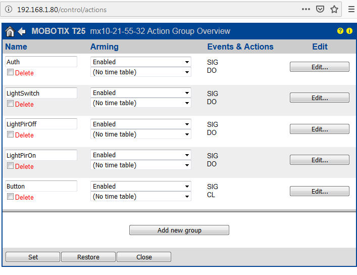
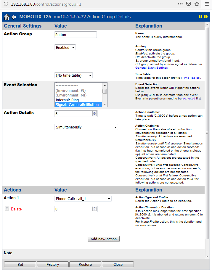
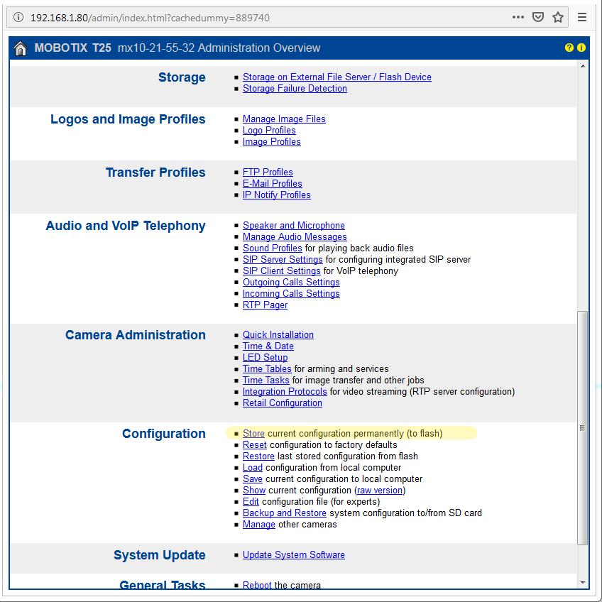
Integration example: Mobotix T25 doorstation
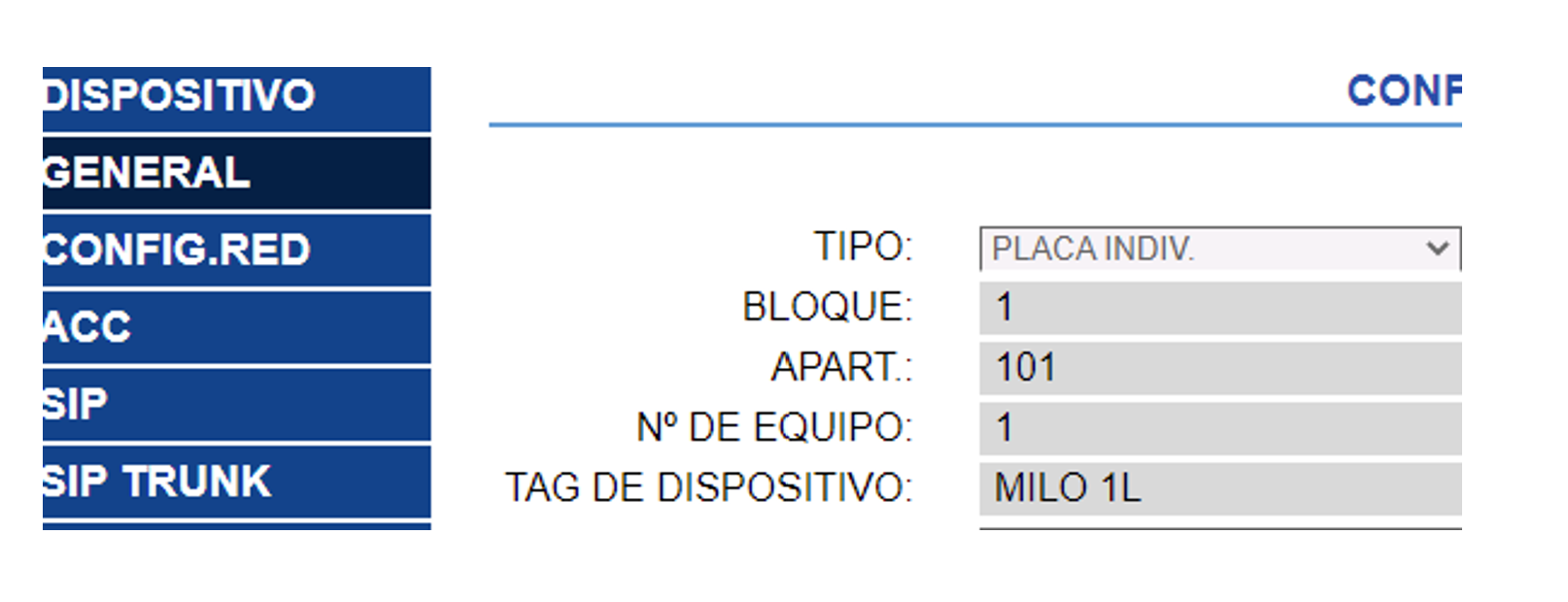
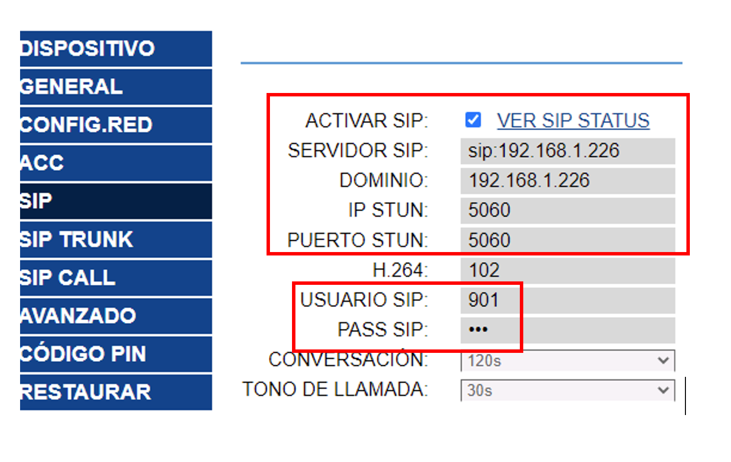
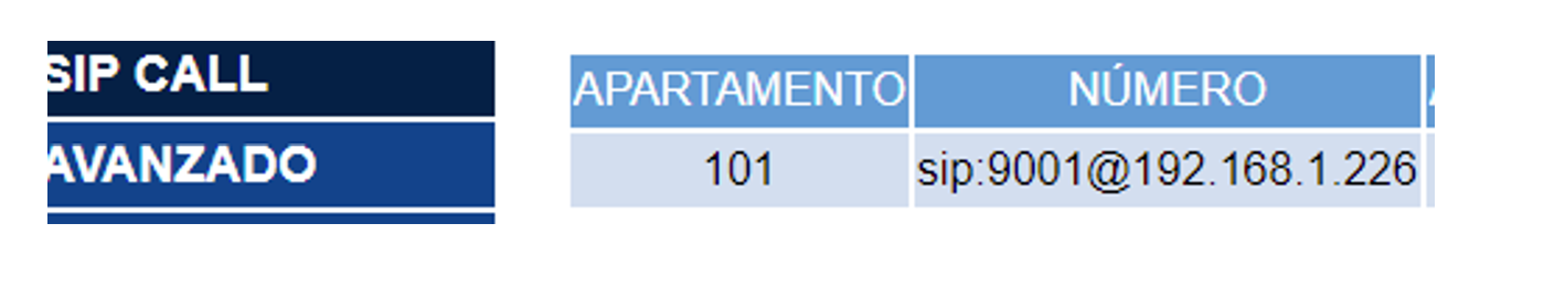
Integration example: Fermax Milo Panel
Integration example: Fermax KIN Panel