Table of Contents
Thinknx Configurator
- Main Concepts
-
Software Download
There are currently two versions of the Thinknx Configurator:
- The Thinknx Classic version (version 1.2.25)
- The Thinknx UP version (version 1.3.0.8), which is an updated version of the Classic with a lot of additional features. To see what’s new in Thinknx UP, check out this section.
Both versions can be downloaded from Thinknx website on this link.
System requirements for Thinknx UP Configurator:
- Microsoft Windows 7 or above
- 64-bit system
- Updated graphic card driver supporting DirectX 10
Main Concepts
Project definition
The Thinknx project created inside the Configurator is defined as a folder containing all the configuration files and settings related to a specific plant. All files imported in the project (such as ETS, images, etc.) are copied and stored in the project folder.
A Thinknx project exported using the Classic Configurator (version 1.2.25) has the extension .erg, while a projet exported using the new UP Configurator (version 1.3.0.8) has the extension .tup.User Interface
ThinKnx Configurator's main window consists of the following elements:
- a toolbar with the main feature for project management
- an interface editor considered as the working area that reproduces the final graphical interface
- Three tabs on the right called Pro Line, Trend Line and System tabs to manage the Interface/System objects.
ThinKnx Configurator's Interface
Clicking on an interface object inside the graphic editor or selecting it from the tree view will show the list of properties related to this object to the right and allow the user to edit it. It is possible to select multiple objects by clicking on them while holding the SHIFT button down. The first selected object will appear with a white bounding box whilst the following selected objects will be bounded with a blue box. In the UP version of Configurator, it is possible to edit the common properties for the selected objects at once. When arranging multiple objects selected (for example, Align Left operation), the first object will always be used as reference.
Toolbar
The toolbar is a set of commands to manage and edit the project as well as the elements inside it, search for items within the project and deploy the project to server and client.
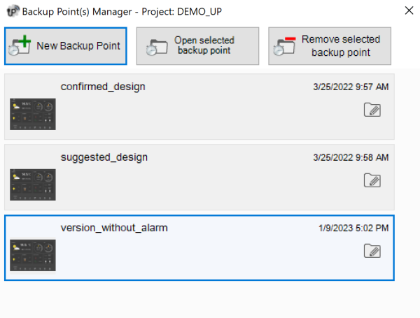
- Projects Access the project manager window. The user can create/open/close/rename/import/export/clone/delete a project. Multiple backup points can be created for the same project if additional tests need to be done without ruining the stable version of the project. Any version can be restored by clicking on the folder icon next to each project and accessing the Backup Points window. For more details on how to create and deploy a Thinknx project, refer to this section.
Project Manager Window
Figure 3: Project Backup Points
- Save Save the current project.
- Add Add objects to the project. The selection of objects changes depending on the tab selected in the right pane (ProLine/TrendLine/System).
- Delete Remove the selected object.
- Move Activate the moving function for page elements. Only available for the Classic version. For the UP version, a drag and drop on the object will allow the user to move it.
- Arrange Arrange graphic objects. This function allows to change the order of a selected group of objects or arrange their disposition; When clicking on this button, the following window will be displayed:
Objects arrange tool
- Bring to front: Move an object or a page before all the others.
- Send to back: Move an object or a page behind all the others.
- Bring frontward: Move an object frontward.
- Send backward: Move an object backward.
- Dispose horizontally: Equally distribute horizontal space between the first and the last selected object.
- Dispose vertically: Equally distribute vertical space between the first and the last selected object.
- Align lefts: Align all the objects to the left edge of the reference object.
- Align centers: Align all the objects to the vertical middle line of the reference object.
- Align rights: Align all the objects to the right edge of the reference object.
- Align bottoms: Align all the objects to the lower edge of the reference object.
- Align middles: Align all the objects to the horizontal middle line of the reference object.
- Align tops: Align all the objects to the upper edge of the reference object.
Some arrange tool actions require the selection of multiple objects. To select more than one object it is necessary to hold the SHIFT button down while clicking on the objects to select.
It is very important that the background images, such as floor plans or photographs, are always positioned on the far back (they always have to show at the top of the Interface tree view). This is just to ensure that all the command objects such as light switches or shutter controls are in the foreground and are not covered by the picture (if the picture covers the button you will not be able to use them, even if it is a transparent part of the picture and you see the buttons).
- Copy/Paste Copy or paste pages or objects. They can be selected either on the interface preview or in the interface tree structure and can be pasted in a empty screen portion. Keyboard commands ”Ctrl+C” and ”Ctrl+V” can be used instead of the icon in the toolbar or the right click.
- Clipboard Any copied item or page will be found inside the Clipboard under section “Live Items”. Select the live item then click on Send To Archive. The item will be moved to section “Archived Items”, allowing the user to close the project and paste the item into another project or PC. The Clipboard is a great tool that will help speed up the design phase and allow the user to just focus on the implementation.
Clipboard
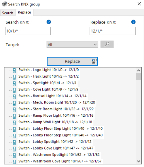
- Search new! Search group addresses within the project; shows a list of objects containing a specific KNX group. Clicking on the newly added Replace tab allows to search and replace one or more group addresses, or part of a group. For example, searching for 0/0/* and replacing it with 0/1/* will replace all group addresses from 0/0/0-255 with 0/1/0-255.
Search and Replace
- Deploy Deploy the project to server and Thinknx client devices using the local network or Thinknx Cloud.
- Translator new! Open the Translator tool, allowing the integrator to translate the Thinknx project into any language. The end-users will be able to switch between languages directly from the Thinknx UP application.
It is important to set one of the languages configured as default before deploying, in order to allow the users to select their own language from the Thinknx UP application. Setting a language as default can be done by clicking on the Languages menu item and selecting “Set Default”.
Translator
Select Language
- Export Open export menu. For more details refer to this section .
Interface editor
It is the work place where the users can build their graphical interface and preview how it will look on the clients. It allows them to add, select and move the objects as desired. Every interface part has its own properties that can be modified from the property editor on the right-bottom side of the Configurator window.
Interface main elements
The user interface is basically composed of the following elements:
- Functions Function is a sort of chapter that can collect several graphical pages. Properties can be easily adjusted from the settings window that is displayed on the right side when selecting a function from the list:
- Status: Permits to disable the function and to hide it from sidebar.
- Label: Name of the function.
- Icon/Graphic: Select the desired icon file to be displayed on the left side of the function's label, with a standard resolution of 60×60 pixels.
- Show in website: Indicates if the function will be visualized on the web page. For more details refer to this section .
- Restrictions: Permits to restrict the access to the function for specific users.
- PIN Protection: If enabled, the function is protected and the user must insert a PIN code to view it. For more details refer to this section .
- PIN Code: Pin code associated to the object.
- Index: The index of the function. Cannot be modified, usually used to redirect a button to this function.
Functions sidebar In the Classic Configurator, this bar appears by touching the blue tag located on the left side of the screen or dragging it to the right, while in the UP Configurator it will be displayed by clicking on the name of the function displayed to the left of the pages; a list of all the functions added to the project is displayed with the function name and the corresponding icon.Pages Each function can contain different editable pages, each one labeled by a tab displayed on the upper part of the screen. Each page created will automatically show up on the top bar starting from the left, the only limitation on the number of pages you can create is the number of characters that can be shown on the top bar. The longer the names of the pages, the less pages you can create. Properties can be easily adjusted from the settings window that is displayed on the right side by selecting a page from the list:- Label: Name of the page.
- Show in website: Indicates if the page will be visualized on the web page. For more details refer to this section .
- Restrictions: Permits to restrict the access to the function for specific users.
- PIN Protection: If enabled, the page is protected and the user must insert a PIN code to see the page. For more details refer to this section .
- PIN Code: Pin code associated to the object.
- Index: The index of the page. Cannot be modified, usually used to redirect a button to this page.
Objects Each page can contain different editable objects. There is a number of graphical objects that represents standard operations that can be exerted (like switching on/off lights, commanding blinds, controlling HVAC). Every object has its own properties that can be customized. For more details refer to Interface Objects .Object Selection
Once objects are added inside the UI, it can be easy to select and move them with the mouse cursor. Clicking and dragging from left to right will select all the objects that are entirely enclosed in the selection border. This is called the Window Selection. Clicking and dragging from right to left will select any object crossed by the selection border. This is called Cross Selection.
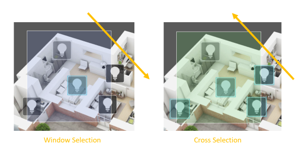
Selection Tool
Pro Line/Trend Line/System tabs
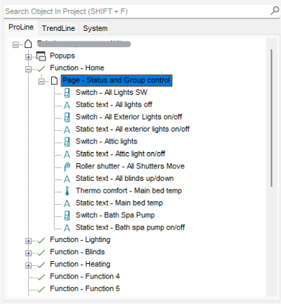
- Pro Line tab: Clicking on the Pro Line tab will show all the user-interface objects added to the current project and supported by the Pro Line application (Thinknx UP); the main node represents the entire user interface while every first level child is a function. Under each function are the pages added and under each page the related objects added to it. Right-clicking on each node will allow the user to add, delete, copy or arrange any interface object (for more details refer to Interface Objects). Selecting an object from the interface editor or the interface tab will show all the related properties in the property grid below the tabs.
Pro Line Tab
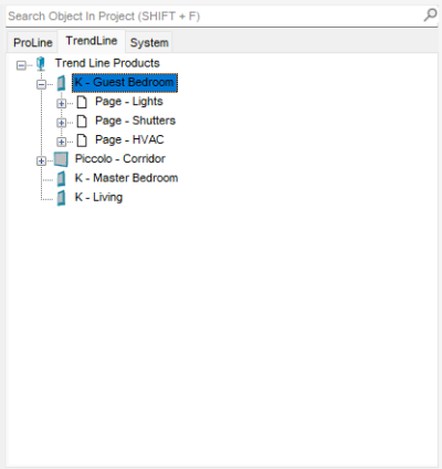
- Trend Line tab: Clicking on the Trend Line tab will show all the Trend Line devices added to the project and permit to configure them. Adding a new Trend Line device is also possible from this tab by right clicking on the title and selecting “add device”. Once the device added, right-clicking will permit to add objects to this device such as pages and page elements.
Trend Line Tab
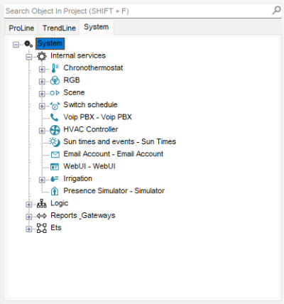
- System tab: Clicking on the system tab will show all the system objects added to the current project; the main node represents all the generic and most important data related to the server and project. Right-clicking on the system tab will allow the user to add any system object. Clicking on an existing system object will show all the related properties in the property grid below the tabs. For more details refer to System Objects .
System Tab
Licenses
The licence editor displays the list of available licences that can be purchased and selected by the customer; bundles or single licences can be selected by ticking the box next to the item. Clicking on any licence will show a brief explanation of the selected item on the right side of the window.
To access the license editor, click on the System tab, and select licenses from the properties window as seen in figure 10. The license editor will also show up when creating a new project inside the wizard (for more details refer to this section).
Accessing the license editor
License editor
With the UP configurator version 1.3.0.16, the standard licenses are automatically selected based on the server model configured in the System tab. Any additional license added to the server will have to be manually selected in the optional licenses section as seen in figure 15.
When using previous versions of the UP Configurator (version 1.3.0.15 or before), it is strongly advised to set licenses in the Configurator according to the real available licenses on the server. This will guarantee that a project exported without warning from configurator will run at once on the server.
Example: Suppose that for a particular server the enabled licenses are: Security and Intercom package, Audio/Video licence and Web licence with 4 clients. These licenses should be ticked in the licence editor and the number of clients has to be typed in the box in the upper right. If an IR transmitter object is added to the project, a window with the following warning is displayed on the screen:Not supported device for selected licenses warning
This warning indicates that the object at issue will not be working once the system will be activated but it will not block project exportation.
Users and Groups
Users and groups allow to generate different settings and interface profiles in the same project. To create, edit or delete users or groups, select the ”System” object and then click on the ”Users and Groups” property. Click on the button on the right to access the editor.
Users and groups editor
To create a new group, click on the ”New group” button. A new item with a default name will be displayed in the users tree. To edit the name, click on the item and adjust the properties in the grid to the right.
Adjusting the properties for a Group will apply to all the users under this particular group.- Name Group or user name.
- ThinknxCloud password Only visible for the user. It is the individual password associated to this user in the ThinknxCloud service. Two users cannot have the same password.
- Display cursor If disabled, the cursor will not be displayed (valid only for Windows/MacOs clients).
- Full screen If enabled, the application will be displayed full screen (valid only for Windows/MacOs clients).
- Sound on click If enabled, a beep will be emitted at every mouse click.
- Block swipe Determines whether advanced gestures are supported by touch devices (not valid for iOS clients).
- Show status bar Determines if a status bar is displayed in client applications (only for iOS clients).
- Reduce long press If disabled, the user can interact with the client using the default long press (e.g. 4 sec for iPad, 3 sec for Android); if enabled, the long press activation time will be reduced to 1.5 sec.
- SIP client Determines if the VoIP function is enabled. If enabled, the following properties will be displayed:
- SIP Ringtone Allows to set the ringtone to be played on the client device when the device is called from another SIP device.
- Use client random port If enabled, use random listening port on clients in order to avoid any possible conflict between VoIP applications.
- SIP protocol Determines the protocol to be used for SIP messages sending. TCP is mandatory for iOS devices to work in background mode. The UDP protocol is mandatory for some PBX servers.
- Register Determines if the client will register on an SIP register (PBX). If enabled, the following properties will be displayed:
- PBX system: If enabled, the ThinKnx internal PBX will be used and the client will be one of the PBX users created on the PBX system object (refer to this section ). If disabled, the client will try to register to a third party PBX and the following properties will be displayed:
- SIP username: SIP client username used during registration process.
- SIP password: SIP client password used during registration process.
- Register address: IP address or hostname of the third party registrar (PBX).
- Register port: UDP port number of the third party registrar (PBX).
Inactivity timer If enabled, this properties allows to configure a specific page that will be automatically reloaded by the client after a preset time interval if the user doesn’t interact with the client; the ”Inactivity interval”, ”Inactivity function” and ”Inactivity page” properties will be displayed.Inactivity interval User’s inactivity time interval after which the system automatically redirects to the selected page. (If the user taps the screen the inactivity timer is automatically reset.)Inactivity function Index of the function which the default page belongs to. (starting from 0)Inactivity page Index of the default page. (starting from 0)Show scheduler if enabled, it will show an icon in the client application to open the Scheduler Manager on the top right corner of the interface. When disabled, the icon will not show and the client will not have access to the scheduler.Scheduler Pin protection if enabled, it will show a new proprieties to add the pin to the schedulerUse Navigation Bar if enabled, it will add on the top right of the client a Home button or a back button to return to the home page or previous pageUse Favourites if enabled, it will add on the top right of the client a Star button. The end user can create a personalized page and add any object present on the application to have is personalized page.Record client specific if enabled, the client specific command(ie: change page) will be included while recording scenes.Access wallet if enabled, the user will be allowed to access wallet informations(via vai object).View logs if enabled, the user will be allowed to access logs.Access control management if enabled, the user will be allowed to manage access control.Reset pin permission if enabled, the user will be allowed to reset the pin codes from the pin keypadsTo create a user already associated to a previously created group, select the destination group and click on the ”New user” button. Doing so, the user takes the property values from the group. To rename the user, select it from the user tree and adjust the ”Name” property in the grid to the right.
To create an independent user, click on the ”New user” button without selecting any group.
Users can be associated to a group at a later moment by dragging them on the desired group.
To delete a group or a user, click on the ”Delete object” button after selecting it. Configurator requires a deleting confirmation; click on ”Yes” if the item has to be cancelled.
When deleting a group, all associated users are automatically turned into independent users. If some objects integrated into the plant contain restrictions for the specific group or user, which has to be deleted, a warning message with the list of objects containing a restriction is displayed; if deletion is confirmed, restrictions for the group or user are removed too.Add a new user to a group
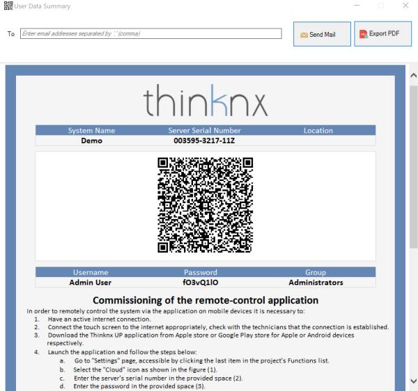
To export the user information or share them by email or QR code, click on the User Data Summary button. A new window will open allowing you to enter the email addresses you wish to share the information with or export the file as PD by clicking on the Export PDF button. A QR code is also available and can be scanned directly from the Thinknx application to download the project automatically with the correct user profile.View and export user information
Restrictions
Sometimes it is requested that a group of users are prevented from viewing and accessing certain functions, pages or elements inside a page. This is possible by first creating the users in System tab, then going to the function in the interface tree, selecting the ”Restrictions” property in the grid and clicking on the button to the right.
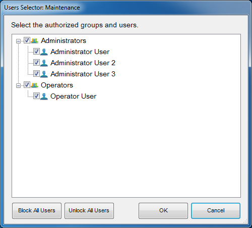
Restrictions editor for functions/pages/objects
In the restrictions editor all previously created users and groups are displayed. By default, all objects do not have any restrictions created, that's why when the editor is launched for the first time, all items are checked to enable the users to access the object selected.
Suppose that all the users who are part of the ”Operators” group have to be blocked; un-checking the box displayed next to the group name and clicking “OK” would be enough to create this restriction. When the project is exported to the users under Operators, the selected function will not be visible for them. Two more buttons, useful to speed the configuration process up, can be found in the editor: ”Block all users”, which sets a total restriction on the object (removes all ticks) and ”Unlock all users”, which removes any restriction previously set on the object.
All restrictions have a priority order: function, page, single object. If a restriction for a group of users is set on one function, the whole function will not be exported even if the same restriction is not set for the objects contained in that function.
Protection PINs
If all objects inside the project must be visible to all the users but some of them still requires some protection, it is possible to use a protection PIN on the desired object.
Inside the project, it is possible to create a list of PIN codes to use in the client application to protect interface objects. To create, edit or delete PIN codes, select the ”System” object and then click on the ”Protection PINs” property displayed in the grid below; then click on the button to the right to access the editor.
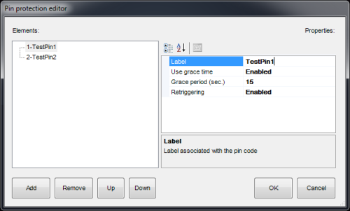
Protection PIN editor
To create a new PIN, click on the ”Add” button. A new item with a default name will be displayed in the list. To edit the name, click on the item and adjust the properties in the list to the right.
- Label Name of the PIN code.
- Use grace time If enabled the inserted code will be valid for the period set in the ”Grace period” property and the client won’t be asked about the code until the grace period expires.
- Grace period (sec.) Period in seconds during which the inserted code is valid.
- Retriggering If enabled, every time the user taps on the object while the grace period is valid, the grace time is renewed.
To associate PIN codes to functions, pages or interface objects, select the desired object in the interface tree, select the ”Pin Protection” property in the grid and enable it. The ”PIN code” property will appear and the list of pins previously created in the System node will appear.
The default value of the PIN code is 12345
One PIN code can be associated to different objects but an object can only contain one PIN code.
PIN protection is valid only with user driven actions; actions like automatic page change are not subjected to PIN protection.
The user can change the PIN code directly from the client app. To reset all pins to the default values, connect to the server's web page and press the “Reset all pins” button inside the “Server→Users” page.
When “PIN protection” is set to “Enabled” and the “Switching type” property of the switch object assume one of following values, the grace time must be enabled and set.
- OFF on pression
- OFF on pression, ON on release
- ON on pression
- ON on pression, OFF on release
- Value on pression
- Value on pression and on release
In the client's application, at the first press of the object, the keypad will appear; once the code is inserted, the switch will unlock. To execute the desired action, the user has to press the switch a second time, after the unlock procedure. The switch will stay unlocked within the “Grace period”. After the “Grace period”, since the switch will lock, the “PIN code” will be requested again.
Security Password
Security passwords are safety passwords stored on the server, used for cameras. The system integrator can configure any security password, and on the user side (with an admin user), it can later be changed to maintain a high level of security.
Security Password
Biometric Protection
Another way to protect the elements inside the project is through the Biometric Protection parameter. When enabled, the object will remain visible in the application, but will require face or fingerprint verification in order for the user to activate the command.
KNX Groups
Within Thinknx system, KNX groups can be divided into two main categories: read and write groups.
Read groups can contain many KNX addresses: addresses must be divided by “;”. The status of the object will assume the value passed by the last telegram received by one of the addresses in the group.
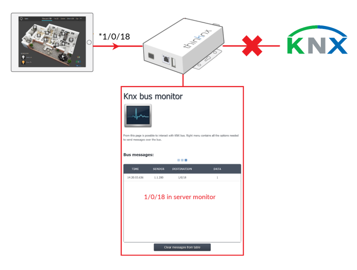
Write groups have just one address. For each write group address, it is possible to disable the sending on the KNX bus by either ticking the option inside the ETS window, or by placing an asterisk before the group address. This will allow the user to run a simulation mode where it is possible to change the status of this group without generating a traffic on the KNX bus. The group will only be seen on the KNX monitor of the Thinknx server.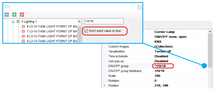
Disabling the sending on the bus
Disabling the sending on the bus


