Table of Contents
Ports Configuration
Compact
The below numbers should be used inside the Configurator when using one of the ports on the Compact:
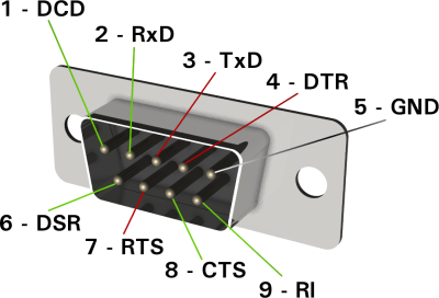
- RS-232 (DB9): use 0.
- USB: use 10.
Rack
The below numbers should be used inside the Configurator when using one of the ports on the Rack:
- RS-232 (DB9) x2: use 0 and 1.
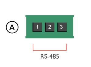
- Additional green ports (RS-232 and RS-485): use 2 and 3.
- USB: use 10.
The additional green ports on the Rack can be used either for RS-232 or RS-485. Consult the picture below for a proper connection.
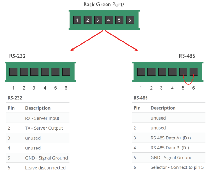
Rack's Green Ports
Brickbox
The below numbers should be used inside the Configurator when using one of the ports on the Brickbox:
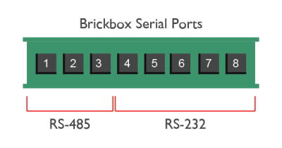
- RS-232: use 4.
- RS-485: use 5.
Envision_20
The below numbers should be used inside the Configurator when using one of the ports on the Envision_20:
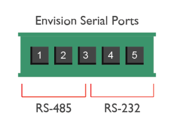
- RS-232: use 1.
- RS-485: use 2.
- USB: use 10.
Compact_20
The below numbers should be used inside the Configurator when using one of the ports on the Compact_20:
- RS-232: use 4.
- RS-485: use 5.
- USB: use 10.
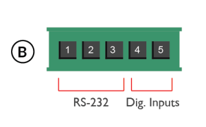
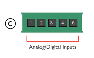
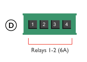
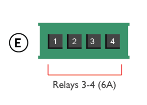
Compact_20 Front/Back Panels
| RS-232 | Dig. Inputs | ||||
|---|---|---|---|---|---|
| Pin | Description | Pin | Description | ||
| 1 | GND - Ground | 4 | Digital IN1 | ||
| 2 | RX - Receive Data (IN) | 5 | Digital IN2 | ||
| 3 | TX - Transmit Data (OUT) | ||||
| Analog/Digital Inputs | |||
|---|---|---|---|
| Pin | Description | ||
| 1 | Input 1 | ||
| 2 | Input 2 | ||
| 3 | Input 3 | ||
| 4 | Input 4 | ||
| 5 | Input - GND | ||
| Relays 1-2 | |||
|---|---|---|---|
| Pin | Description | ||
| 1 | Common R1 | ||
| 2 | Relay 1 (N.O.) | ||
| 3 | Common R2 | ||
| 4 | Relay 2 (N.O.) | ||
| Relays 3-4 | |||
|---|---|---|---|
| Pin | Description | ||
| 1 | Common R3 | ||
| 2 | Relay 3 (N.O.) | ||
| 3 | Common R4 | ||
| 4 | Relay 4 (N.O.) | ||
Micro_20
The below numbers should be used inside the Configurator when using one of the ports on the Micro_20:
- USB: use 10.
Examples
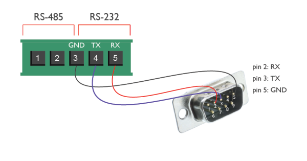
Connecting a DCE device with DB9
A DCE device usually has the pins TX and RX inverted (TX on pin 2, RX on pin 3).
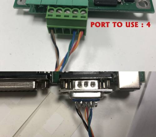
Connecting Brickbox to Paradox DB9 port
