Table of Contents
Logic Module
Each logic scheme consists of a sheet containing different functional blocks, called nodes. Each node corresponds to a specific function executed by the Thinknx server.
The behavior of a node is determined by its connectors, which represent its inputs and outputs. Nodes can be linked together through connections: each connection starts from an output connector and ends at an input connector of another node.

This page describes the general operation of the Logic Module. For the configuration and behavior of an individual node, select the corresponding link in the following sections.
Quick access
Scheme management
The logic scheme can be managed using the following buttons in the toolbar:
- Import: imports the block diagram contained in an XML file into the current logic scheme.
The import operation completely overwrites the current logic scheme.
- Export: exports the current logic scheme to an XML file, which can then be imported into other logic schemes.
The export operation does not save the scheme inside the Configurator. It only generates the corresponding XML file.
- Save: saves the current logic scheme inside the Configurator project.
- Close: closes the Logic Module editor.
Simulation management
The simulation feature allows the behavior of the block diagram to be tested and analyzed before or during its execution on the Thinknx server.
Two types of simulation are available in the Logic Module:
- Offline Simulation: executes the block diagram directly inside the Configurator and displays, in real time, the values passing through the node inputs and outputs. This makes it possible to test the behavior of the scheme by manually setting the input values.
- Online Simulation: connects to the Thinknx server and displays directly in the Configurator the values processed by the block diagram running on the server.
Offline Simulation can be used to test the behavior of the scheme, but it does not communicate with the KNX bus or with the real system objects. Input values must be simulated manually.
Online Simulation works only when the computer running the Configurator is connected to the same local network as the server.
The address used for the connection corresponds to the Local IP address configured in the System object.
During a simulation, the value display can be configured by selecting Sim. Settings in the toolbar.

The following options are available:
- Force show value labels for all connectors: keeps the labels containing the current values of all connectors permanently visible. If this option is disabled, a label is displayed only when the corresponding connector value is updated.
- Value updates fade timeout: if permanent label display is disabled, this property determines how long the latest received value remains visible.
Nodes, connectors and connections
Creating a node
To create a node:
- Open the Node Types Library.
- Locate the required node type.
- Drag the node into the logic scheme sheet.
- Select the node to configure its properties.

Editing a node
When a node is selected, its properties are displayed in the property grid.
Changing these parameters modifies the behavior of the node.

Each connector also has its own properties. To edit them, select the connector directly: the corresponding parameters will be displayed in the property grid.
Multiple nodes can be selected by holding down the Shift key.
Deleting a node
To delete a node:
- select it and press the Del key; or
- move the pointer over the node and select the small X icon displayed on it.

When a node is deleted, all associated connections are automatically removed.
Creating a connection
To create a connection between two nodes:
- Select an output connector.
- Hold down the mouse button.
- Drag the connection to the input connector of the destination node.
- Release the button when the green confirmation symbol appears.

Connections can be created only between:
- an output connector;
- an input connector belonging to another node.
An output connector can be linked to multiple input connectors. An input connector can receive only one connection.
Data compatibility
A connection is not prevented when the output data type differs from the type expected by the input. The received value is automatically converted according to the following rules:
| Conversion | Rule | Example |
|---|---|---|
| Bit → Number | Logic 0 (False) is converted to the number 0, while logic 1 (True) is converted to the number 1. | True → 1 |
| Number → Bit | The number 0 is converted to 0 (False). Any other numeric value is converted to 1 (True). | 25 → True |
| String → Bit | The string is converted to 1 (True) only if it contains 1 or true. In all other cases, it is converted to 0 (False). | “true” → True |
| String → Number | The string content is converted to a numeric value if it uses a valid format. | “25.5” → 25.5 |
Gate connector
Except for input and output nodes, nodes can be enabled or disabled through the Gate connector.
To display this connector, enable the Gate property of the node.

When a node is disabled:
- the calculation is not performed;
- no values are sent to the output connectors;
- new values received by the input connectors do not produce any result.
The following properties can be configured by selecting the Gate connector:
- Inverted gate:
- when disabled, the node is enabled when Gate = 1 and disabled when Gate = 0;
- when enabled, the behavior is inverted: the node is enabled when Gate = 0 and disabled when Gate = 1.
Force output sending: when the node is enabled, all output connector values are refreshed regardless of the Output sending behavior configured for the individual outputs.When the Gate property is enabled but its connector is not connected, the node is disabled by default.
The node also remains disabled when the Gate connector is connected but has not yet received a value from its source.

Await all inputs
The Await all inputs property is available for individual blocks in the logic scheme.
When set to True, the node waits until all its inputs have received at least one value before performing the calculation and producing a result.
This property prevents the node from being processed using incomplete data or inputs that have not yet been initialized.
Input nodes
Input nodes allow the scheme to acquire values from the installation, System objects, or constants defined directly in the scheme.
- Constant Value: provides the scheme with a numeric, logic, or text value defined during configuration.
- KNX Input: acquires the value associated with a KNX group address from the KNX bus.
- Sheet Input: represents a generic input of a reusable logic function.
- Internal Status: acquires a status made available by a System object configured in the project.
Output connector
Input nodes have a single output connector through which the acquired value is transmitted.
The Output sending behavior property determines when the value is forwarded to the connected nodes:
- On result change: the result is sent only when it differs from the previous value.
- When a new input telegram is received: the result is sent whenever the server receives an update from the input source, even if the value has not changed.
During an offline simulation, input updates can be simulated by manually entering values in the corresponding toolbar panel.
Output nodes
Output nodes represent the final action performed using the values processed by the scheme, such as sending a KNX telegram or executing a command.
- Command: executes the configured command when a value or trigger signal is received.
- KNX Output: sends the value processed by the scheme to a KNX group address.
- Sheet Output: represents a generic output of a reusable logic function.
Input connectors
The input connectors of output nodes include the Trigger property.
When this property is enabled, receiving a new value on the connector starts the action configured in the output node.
Analog nodes
Analog nodes process numeric values, perform regulation, apply filters, and check whether configured thresholds have been reached.
- Comparator / 2 Points Regulator: compares two numeric values using two switching thresholds and maintains the previous state while the difference remains between them.
- PID Controller: regulates the output according to the difference between the setpoint and the measured value.
- Pulse Width Modulator: converts an analog value into a pulse signal whose ON/OFF ratio is proportional to the received value.
- Ramp: progressively increases or decreases the output until the requested value is reached.
- Range Verifier: checks whether the received value is included between a minimum and maximum threshold.
- Automatic Thermostat: automatically manages thermostat regulation according to the configured modes and values.
- Thermostat Setpoint: determines or modifies the setpoint used for thermostat regulation.
- Threshold Filter: limits the output value according to the configured minimum and maximum thresholds.
- Time-based Filter: filters or delays value transmission according to the configured time conditions.
Counter nodes
Counter nodes receive a numeric or logic value, perform a counting operation, and provide the result through their output connectors.
- Maintenance Counter: measures the total time during which the input remains active.
- Up/Down Counter: increases or decreases a value in response to the rising edges received on the corresponding inputs.
- Statistic Meter: calculates and stores current and previous daily, weekly, monthly, and yearly totals.
Output connectors
The output connectors of counter nodes include specific properties that determine when calculated values are sent.
The Output sending behavior property provides the following options:
- On new value reception: the value is sent whenever the node updates the result.
- After a fixed time interval: the value is sent when the configured interval expires, regardless of whether it has changed.
- On over-threshold change: the value is sent when its percentage difference from the previous value exceeds the configured threshold.
- On over-threshold change and after time: the value is sent when the change threshold is exceeded and, in any case, when the configured interval expires.
The associated properties are:
- Store time interval: time interval to wait before sending the value.
- Change percentage: minimum percentage change required to send the value. The new value must differ from the previous one by more than the configured percentage.
Logic nodes
Logic nodes process binary values.
Except for nodes with a fixed structure, the number of inputs can be changed using the Number of inputs property.
- AND: returns 1 only when all inputs are equal to 1.
- Filter: forwards, modifies, or blocks the received value according to the configured filtering mode.
- IF: selects one of two input values according to the state of the condition.
- Latching Relay: maintains the output state and allows it to be changed using the Set and Reset inputs.
- Logic Matrix: transfers the value of a selected input to a selected output.
- Memory: stores and provides the latest value received according to the configured conditions.
- NAND: returns 0 only when all inputs are equal to 1.
- NOR: returns 1 only when all inputs are equal to 0.
- NOT: inverts the logic value received at the input.
- OR: returns 1 when at least one input is equal to 1.
- Pulse Relay: maintains the output state and toggles it whenever a rising edge is received on the Trigger input.
- XAND: returns 1 only when all inputs have the same value.
- XOR: returns 1 when the inputs have different values.
Input connectors
The input connectors of logic nodes include the following properties:
- Trigger: when enabled, receiving a new value on the connector triggers the node calculation and the possible transmission of the results.
- Inverted input: inverts the value received by the connector. When the input is inverted, a red symbol is displayed beside the connector.
Output connectors
The output connectors of logic nodes include the following properties:
- Output sending behavior:
- On result change: the result is sent only when it differs from the previous one;
- When a new input telegram is received: the result is sent whenever the source updates an input.
Inverted output: inverts the transmitted value. When the output is inverted, a red symbol is displayed beside the connector.Timer nodes
Timer nodes perform time-based operations, apply delays, and generate pulses or timed sequences.
- Date and Time Converter: divides a value containing a date or time into its individual components.
- On/Off Delay: applies independent delays to the rising and falling edges of the signal.
- Continuous Pulse Generator: continuously generates pulses with configurable ON and OFF times while the Gate connector is active.
- Pulse Train Generator: generates a sequence containing a configurable number of pulses.
- Random Pulse Generator: generates pulses with random ON and OFF times within the configured ranges.
- Scheduled Pulse: generates a pulse at a configured time.
- Stairwell Lighting Switch: keeps the output active for the configured time and can provide a warning signal before switching it off.
- Stopwatch: measures partial intervals and the total accumulated time.
Math nodes
Math nodes perform arithmetic operations on the values received at their inputs.
- Absolute Value: calculates the absolute value of the received value.
- Addition: calculates the sum of n values.
- Average: calculates the arithmetic mean of n values.
- Division: calculates the division of two values.
- Linear Combination: calculates the linear combination of the inputs using the configured weights.
- Logarithm: calculates the logarithm using the base and argument received at the inputs.
- Math Expression: calculates a custom mathematical expression.
- Maximum: returns the maximum value among the inputs.
- Minimum: returns the minimum value among the inputs.
- Multiplication: calculates the product of n values.
- Power: performs exponentiation using a base and an exponent.
- Remainder: returns the remainder of the division of two values.
- Round: rounds the received value to the closest integer.
- Subtraction: calculates the subtraction of n values.
Scripting node
The Scripting Node allows users with basic programming knowledge to freely create operational logic using the integrated IDE.
The script code defines the algorithm to be executed, its input parameters, and any output values.
For the method syntax, parameter definition, and usage examples, refer to the Scripting Node page.
Reusable logic sheets
The Sheet Input, Sheet Output, and Logic Module Sheet nodes can be used to create generic logic blocks, export them in XML format, and reuse them in other projects.
This feature makes it possible to standardize recurring logic and divide a complex scheme into multiple functional blocks.
For the complete procedure, refer to Sheet Input, Sheet Output and Logic Module Sheet.
Comments
The Comment node can be used to add text annotations to the sheet, making the logic scheme easier to document and understand.
Comments do not participate in logic processing and do not have connectors.
Scheme verification
Before saving the scheme and transferring the project to the server:
- Verify that all required inputs receive a value.
- Check the Trigger properties of the connectors.
- Verify the configuration of any Gate connectors.
- Check whether nodes requiring multiple inputs should use the Await all inputs property.
- Use Offline Simulation to verify the results produced by the scheme.
- Verify that there are no unintended circular connections.
- Check that the data types and automatic conversions produce the expected results.
- Save the scheme using the Save button.
- Transfer the project to the server and, if necessary, use Online Simulation to verify its actual behavior.
Pay particular attention when the input and output of a logic scheme use the same source, for example the same KNX group address. An incorrect Trigger configuration may generate a continuous update loop.
Logic examples
Temperature regulator
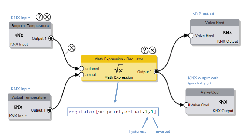
Example 1: Temperature Regulator
Using the Math Expression node and the
Regulatorfunction, it is possible to implement a regulation based on a setpoint and the actual temperature value.The two additional expression inputs represent:
- the hysteresis value;
- the option to invert the result:
- 0 = normal operation;
- 1 = inverted result.
In this example:
- if Setpoint > Actual, the value 1 is sent to Heat Valve and 0 is sent to Cool Valve;
- if Setpoint < Actual, the value 0 is sent to Heat Valve and 1 is sent to Cool Valve.
For more information about configuring expressions, refer to the Math Expression page.

