Table of Contents
System Objects
- System new!
- Internal ServicesSecurity
- Reports and Gateways
- Ethernet Gateway new!
- OpenWeatherMap new!
- MQTT Server new!
- MQTT Client new!
- Gateway FIAS new!
System

This object is the main node of the system tree and includes all the main features and data that describe the project. All other objects, which represents the configurable services provided by the server, can be added to the project by right clicking on this node.

Example of system graphical editor
- Label Name of the object.
- Graphics Editor Edit the server settings using a graphical editor.
- Server type Type of server and hardware (Brickbox, Compact, Compact-20, Envision, Micro, or Rackmount server).
- Serial number Server serial number printed on the box.
- Password Password for service user, to log in to the web server page.
- ThinknxCloud If enabled, cloud services are active. Enabling this option allows uploading the project directly to the Cloud and storing variables in the database.
- Password for ThinknxCloud: Maintainer password of the cloud services. It can be managed from the server web pages.
Automatic server update If enabled, the server will automatically download the project from the cloud whenever the project is uploaded to the cloud.Automatic authentication If enabled, the final user can authenticate the client automatically from the app using the username and cloud password of the User and Group Property.Use OTP authentication Enable management of OTP codes, allowing you to link a created client with a device that is trying to connect to the server.Automatic connection If enabled, the connection of client apps to the server is totally automatic and managed through ThinKnxCloud.- Local and Cloud Whenever the local connection fails, the client apps will try to connect to the server using ThinKnxCloud.
- Local,Remote and Cloud Whenever the local connection fails, the client apps will try to connect to the server first through the remote IP of the server with the External Port specified in the configurator. If it fails, the connection will pass through ThinKnxCloud.
KNX address Physical address (es. xx.xx.xxx) assigned to the server; if not specified it is automatically assigned by the system.External IP address IP address (for example, 74.14.3.108) or hostname (for example, pulsar.dyndns.org) needed to connect with the server from clients that do not operate on the server LAN. To set up the server with the ThinKnx cloud server, refer to the Cloud section.Server client port Number of the TCP port needed to remotely connect with the server (outside the server network. External IP Port, internally is 7550). The default port is 7550.Local IP address IP address (for example, 192.168.X.X) needed to connect with the server from clients that operate on the server LAN.KNXNet/IP interface If enabled, the Thinknx server can be used as a KNXNet/IP interface, allowing KNX programming from the ETS software, for example. More information is available in the KNXnet/IP guide.KNXNet/IP different IP If enabled, permits choosing a different KNXNet/IP interface to connect and access the KNX bus.Clients Ph. Address Base Base physical address for the client connections. If there are connections, the server will progressively occupy physical addresses for the number of decided clients.Client number Number of supported client tunnel connections.KNXNet/IP router If enabled, the server will also route traffic from TP to multicast IP and vice versa, allowing connection of different parts of a KNX system together over IP. More information are available on the KNXnet/IP guide.System name Name to identify the project once it has been uploaded to the server.Location Insert the name of the location then click on the three dots for auto compiling the latitude and longitude OR Clicking on the three dots(without the name of the location) for opening the location search tool then Enter the address to set the desired location.
- Latitude Latitude of the location where the server is installed. It is used to enable the iOS geolocation function and the sun time events .
- Longitude Longitude of the location where the server is installed. It is used to enable the iOS geolocation function and the sun time events .
- Send command after reboot It is possible to launch a command on server full reboot or soft restart after a predefined time interval. If soft restart is selected, the command will be executed also when a new project version will be uploaded. Sending a command after a full restart could be useful to notify blackouts. If the property “Send command after reboot” is not disabled, the following properties will appear:
- Command delay: Time in seconds between the complete reboot of the server and the execution of the command.
- Command: Command to send after the server reboots.
Automatic reboot When enabled, allows the user to schedule reboot time- Scheduled Time Open a popup to schedule the reboot time.
Time server If enabled, the server will send date and time information to the bus, and “Time group” and “Date group” properties will be displayed:- Time Group: KNX time group address to receive or send time information.
- Date group: KNX date group address to receive or send date information.
Licenses Active licences for the current project, for more details refer to Thinknx Configurator - Licenses .Users and Groups Groups and users for the customized exporting process, for more details refer to Thinknx Configurator - Users and Groups .Protection PINs List of PINs used to protect interface objects, for more details refer to Thinknx Configurator - Protection PINs.Secutiry Passwords Stored custom password that can be use to protect Alarm Device and Camera object, for more details refer to Thinknx Configurator - Security Password.Ask for old password If enabled for changing password, it will be necessary to insert the previous password.Share Messages Open a pop up menu to edit the messages wich will be sent when sharing a project.Warning header color Customize the color of the header to show warningsPreview header Runtime Preview of the header color when an error occursObject Commands
Commands sent to the object and recallable from other objects:
If Send KNX Bit telegram (DPT 1) is selected
This command is used to send a 1 bit value to the KNX bus.
- KNX Group Group address to sen the value.
- KNX value Can be either 1 or 0.
If Send KNX 4 Bit Telegram(DPT3) is selected
- KNX Group Group address to send the value.
- KNX value Can be a value between 0 and 15.
A generic button can be configured to decrease (value 0-7) or increase ( value 8-15) a light dimming value. It can also be used to change a shutter position (use values 0-7 for UP, and 8-15 for DOWN). For example, sending the value 5 to a dimmer will decrease the brightness by 6%, while sending the value 10 to a shutter will lower its position by 50%.
If Send KNX Byte unsigned Telegram(DPT5) is selected
- KNX Group Group address to send the value.
- KNX value Can be a value between 0-255.
If Send KNX Byte signed Telegram(DPT6) is selected
- KNX Group Group address to send the value.
- KNX value Can be a value between -128-+127.
If Send KNX unsigned Integer 2 Bytes Telegram(DPT7) is selected
- KNX Group Group address to send the value.
- KNX value Can be a value between 0-65535.
If Send KNX signed Integer 2 Bytes Telegram(DPT8) is selected
- KNX Group Group address to send the value.
- KNX value Can be a value between -32768-+32767.
If Send KNX Float 2 Byte Telegram(DPT9) is selected
- KNX Group Group address to send the value.
- KNX value Can be a value between -671088,64 and 670760,96.
If Send KNX unsigned Integer 4 Byte Telegram(DPT12) is selected
- KNX Group Group address to send the value.
- KNX value Can be a value between 0-4294967295.
If Send KNX signed Integer 4 Byte Telegram(DPT13) is selected
- KNX Group Group address to send the value.
- KNX value Can be a value between -2147483648 - 2147483647
If Send KNX Floa 4 Byte Telegram(DPT14) is selected
- KNX Group Group address to send the value.
- KNX value Send value to the bus.
If Send KNX String Telegram(DPT16) is selected
- KNX Group Group address to send the value.
- KNX value string text to be entered.
If Send KNX unsigned Integer 3 Byte Telegram is selected
- KNX Group Group address to send the value.
- KNX value Send value to the bus.
This command is used to read a value from the KNX bus.
- KNX Group Group address to read the value from.
This command is used to restart a KNX device.
- Physical address of the KNX device Physical address of the knx device to restart
Make a pause for a fixed interval[msec]
This command pauses the system for a specified time interval configurable in milliseconds.
- Interval Time interval in milliseconds.
When saving a scene, sometimes a pause between two commands is necessary, for example, when saving the TV channel number. Another use of the Pause application would be before turning off the final light in a Goodbye scene, making sure that the client has left the house.
Change UI Function and Page: All Clients
This command allows to redirect all clients to a specific function and page.
- Function choose from the dropdown menu the destination function.
- Page choose from the dropdown menu the destination page.
Using the Universal Gateway, a scenario can be configured to redirect the users to the Main Entrance camera page whenever the doorbell rings.
Change UI Function and Page: SPECIFIC CLIENT
This command allows the specific client who has sent it to access a certain function and page.
- Function choose from the dropdown menu the destination function.
- Page choose from the dropdown menu the destination page.
Invisible generic buttons can be placed on the house plan for each room, allowing every single client to navigate through the rooms by clicking on each area.
This command allows to redirect all clients to a specific pop up
- Popup choose from the dropdown menu the popup
This command allows to redirect a specific user to a specific pop up
- Popup choose from the dropdown menu the popup
- Choose from the dropdown menu the specific user
This command allows the specific client who has sent it to access a certain popup
- Popup choose from the dropdown menu the popup
This command allows to close popup for all clients
This command allows to close popup for a specific user
- Choose from the dropdown menu the specific user
This command allows to close popup for the specific client
Toggle Object Visibility: All Clients
After using the 'find' function to select an object, this command allows you to toggle its visibility for all clients, either showing or hiding it universally.
- Status send 0 for show/ 1 for hide
Toggle Object Visibility: Client Specific
After using the 'find' function to select an object, this command allows you to toggle its visibility for this specific client, either showing or hiding it universally.
- Status send 0 for show/ 1 for hide
Toggle Group Visibility: All Clients
After using the 'find' function to select a group, this command allows you to toggle its visibility for all clients, either showing or hiding it universally.
- Status send 0 for show/ 1 for hide
Toggle Group Visibility: Client Specific
After using the 'find' function to select a group, this command allows you to toggle its visibility for this specific client, either showing or hiding it universally.
- Status send 0 for show/ 1 for hide
Toggle Page Visibility: All Clients
After using the 'find' function to select a page, this command allows you to toggle its visibility for all clients, either showing or hiding it universally.
- Status send 0 for show/ 1 for hide
Toggle Page Visibility: Client Specific
After using the 'find' function to select a page, this command allows you to toggle its visibility for this specific client, either showing or hiding it universally.
- Status send 0 for show/ 1 for hide
Set Warning Header Bar: All Clients
Change the header color. Send 1 to change it to warning, 0 to clean for ALL Client.
Set Warning Header Bar: Client Specific
Change the header color. Send 1 to change it to warning, 0 to clean for a specific user
This command allows to send push notifications to the clients. By accessing the web page of the server and clicking on Server –> Licenses and Codes, it is possible to enable/disable the receipt of push notifications for each client.
- Message insert the message to be displayed on the clients.
- Maximum number of push notifications with the same identifier allowed in 10 min This parameter is not mandatory. However, if a value has been entered, the system will make sure to limit the number of push notifications sent to this number in 10 min. It is quite useful when the trigger for sending the push notifications is being sent frequently on the bus.
- Push Notification Identifier A small descriptive text to allow the system to differentiate a push notification from another one when calculating the rate limit. Mandatory only if the previous parameter has been used.
Using the Universal Gateway, a push notification can be sent to the client when a 1-bit value is received from the bus to indicate that the Water Tank Level is low. The message in that case can be “Low Water Level!”. If the 1-bit is being sent periodically to the bus with a small interval, then a maximum number of push notifications can be inserted in the related parameter.
Push notifications only work with internet connectivity. In addition, the server and client should both have the same version of Thinknx software (both Classic or Thinknx UP).
Send Push Notification user specific
This command allows to send push notifications to one specific user. By accessing the web page of the server and clicking on Server –> Licenses and Codes, it is possible to enable/disable the receipt of push notifications for each client.
- Message insert the message to be displayed on the clients.
- Maximum number of push notifications with the same identifier allowed in 10 min This parameter is not mandatory. However, if a value has been entered, the system will make sure to limit the number of push notifications sent to this number in 10 min. It is quite useful when the trigger for sending the push notifications is being sent frequently on the bus.
- Push Notification Identifier A small descriptive text to allow the system to differentiate a push notification from another one when calculating the rate limit. Mandatory only if the previous parameter has been used.
Using the Universal Gateway, a push notification can be sent to the client when a 1-bit value is received from the bus to indicate that the Water Tank Level is low. The message in that case can be “Low Water Level!”. If the 1-bit is being sent periodically to the bus with a small interval, then a maximum number of push notifications can be inserted in the related parameter.
Push notifications only work with internet connectivity. In addition, the server and client should both have the same version of Thinknx software (both Classic or Thinknx UP).
Execute MS Windows Command: GENERAL
This command allows to launch an .exe file directly from the ThinKnx application on all Players for Windows.
- Command
- Parameter
Execute MS Windows Command: SPECIFIC CLIENT
This command allows to launch an .exe file directly from the ThinKnx application on all Players for Windows.
- Command
- Parameter
This property allows to launch a specific application on iOS devices directly from the ThinKnx app by typing the related URL.
- URL used to recall iOS app Type in the correct URL to open the desired installed application, for example http://www.google.com will automatically browse the google safari page. Another example is typing sonos:// to open the SONOS app.
A generic button can be configured for the client to open another application on the iOS device.
This command allows to send an email message using a default ThinKnx account.
- Email Subject Enter the email title here.
- Email Recipients Enter destination email accounts.
- Email Content Enter the email content here.
If the client's house is empty and a presence has been detected inside (1-bit KNX telegram), a scenario can be programmed on the Universal Gateway to send an email to the owner of the house.
This command might not work properly. Instead, add an Email Account under System tab, and select the command “send email to recipient” that can be found in the Internal Services. See this section for more information.
Send DTMF tone during intercom call
This command allows to send a DTMF tone used in telephony while an intercom call is running on the client.
- DTMF tones sequence enter the sequence of numbers to send during the intercom call. Sometimes it is necessary to end the sequence with the symbol “#”, depending on the application.
A generic button can be configured in the Intercom page to send a DTMF tone to open the main gate whenever a call is established.
When using the Thinknx server as PBX, it is possible to make internal calls between all the devices.
- Extension to call Enter the extension of the destination device.
A house owner can have a generic button on his application to call the extension of the touch screen installed in Kitchen to communication with the help.
Disable the ring of SIP client: All Clients
When using the Thinknx server as PBX, it is possible to disable the ring when someone is calling
- Parameters 0 to enable / 1 to disable
Disable the ring of SIP client: Client Specific
When using the Thinknx server as PBX, it is possible to disable the ring when someone is calling
- Parameters 0 to enable / 1 to disable
Disable the ring of SIP client: User Specific
When using the Thinknx server as PBX, it is possible to disable the ring when someone is calling
- Parameters 0 to enable / 1 to disable
Start audio notification sound in all the clients
This command allows to play an audio sound in all the clients.
- Sound to play Choose between different beeps to play: 0=Beep_1, 1=Beep_2, 2=Alarm_1, 3==Alarm_2, 4=Siren_1, 5=Siren_2.
- Duration of the sound to play Specify the duration of the sound to play in seconds. If 0 is entered, the sound will play endlessly until a Stop command has been sent.
An emergency push button can be installed in bathrooms to send a KNX 1-bit value. Using the Universal Gateway, this value received can launch the command to start audio notification on all clients.
Stop audio notification sound in all clients
This command allows to stop the audio sound previously launched in all clients.
See above command for example.Start audio notification sound in all the clients to a specific user profile
This command allows to play an audio sound in all the clients to a specific user profile.
- Sound to play Choose between different beeps to play: 0=Beep_1, 1=Beep_2, 2=Alarm_1, 3==Alarm_2, 4=Siren_1, 5=Siren_2.
- Duration of the sound to play Specify the duration of the sound to play in seconds. If 0 is entered, the sound will play endlessly until a Stop command has been sent.
- Select a specific user a dropdown menu with all user to select from
An emergency push button can be installed in bathrooms to send a KNX 1-bit value. Using the Universal Gateway, this value received can launch the command to start audio notification on all clients.
Stop audio notification sound in all clients to a specific user profile
This command allows to stop the audio sound previously launched in all clients to a specific user profile.
- Select a specific user a dropdown menu with all user to select from
See above command for example.Command the backlight of Envision clients
- Send 1 to On / Send 0 to off
Command the backlight of Envision clients associated to a specific user
- Command to send Send 1 to On / Send 0 to off
- Select a specific user Select from a dropdown menu the user profile
Command the backlight of Envision clients associated to a specific user
- Command to send Send 1 to On / Send 0 to off
- Select a specific user Select from a dropdown menu the user profile
Navigate Back to previous selected page
This command allows to return back to the previous page
This command allows to change the Language, previously configured, for all clients. For how to set Translation see User Interface
Change Language: Client Specific
This command allows to change the Language, previously configured, for a specific user profile. For how to set Translation see User Interface
This command allows you to change the URl of a web browser object for all clients
- Web Browser a dropdown menu for choosing the Web Browser object
- URL the url
Go to web URL: client specific
This command allows you to change the URl of a web browser object for specif client
- Web Browser a dropdown menu for choosing the Web Browser object
- URL the url
ETS
ETS project

This object contains all KNX groups configured in the ETS software. It simplifies visualization and selection of these groups within the Configurator thanks to a tree displaying. Following properties are displayed in the grid below:
- Label Object name.
- CSV file This property specifies the .csv or .esf file containing the project.
- Automatic encoding if enabled, the system to try to recognize the used encoding for the selected file. In some cases, the encoding is not correctly detected, and it is better to force the encoding manually, bi disabling the “Automatic Encoding”.
- Secondary Interfaces If enabled, it allows the server to connect and communicate with multiple KNX IP interfaces. The server will manage the traffic from each interface using a direct 1:1 KNXnet/IP communication.For more application see KNXnet/IP The same group address can be used with multiple interfaces and can control completely different objects. It is enough to link the Thinknx switch with the group address, followed by “-X”, where X = Interface number. For example, group 0/0/1-1 controls the light on Interface-1, while group 0/0/1-2 controls the light on Interface 2. For each interface added in the editor, the below parameters are available:
- Name: Interface label.
- Interface Number specified by the user. It must be an integer value between 1 and 254.
- Interface IP Address IP address of the secondary interface.
- IP Port IP port to communicate with the secondary interface.
- ETS File The file containing the group addresses of the secondary interface. Both .csv and .esf formats are supported.
If the suffix “-255” is used, the telegram will be sent to all the configured interfaces.

Secondary interfaces communication

Secondary interface configuration
Launch ETS, then right click on ”main groups” (ETS3) or ”Group Addresses” (ETS4) and select the ”export group addresses” option. With ETS 3 use default export parameters, in ETS 4 select CSV format and activate the ”Export header information” flag.

ETS 3 export parameters
With ETS 4 and later versions, the project can be exported in OPC.
From the ETS application, click on “Other → Export OPC”: the generated “.esf” file can be imported in the Configurator at a later time.
Internal Services
Scene

This service allows to define a list of actions to be performed by the server on user’s demand or depending on a specific setting. These actions can be specified by the installer directly in the Configurator or in the client application by the user.
This object can be linked to a Scene icon in the user interface, or used internally with the logic module, universal gateway and others.
- KNX group KNX group address used to recall the scene.
- KNX Data Type Data type of the KNX group address used to recall the scene. The telegram used to recall the scene can be of two types: DPT 1 (Boolean - 1bit) or DPT 17-18 (Unsigned Integer - 1 byte). In case of 1 bit telegram, the scene is recalled whenever the ThinKnx server receives 1 on the KNX group; otherwise, in case of 1 byte telegram, the scene is recalled whenever the ThinKnx server receives the value specified in the following property.
- Record This property has to be enabled when the user is creating a customized scene; if he is selecting actions from the default list, this property can be disabled.
- Restartable If enabled, the selected scene can be restarted if launched when already running; it is useful when the scenes is full of pauses and it is particularly long-lasting; when the scenery is launched from KNX, this property has to be disabled because of telegram repetitions.
- List of actions By clicking on the button displayed on the right, the action editor will be displayed; the user can add the desired number of action by clicking on ”Add” button. Each action can be given a name and the related command can be selected by clicking on the button displayed on the right side of the dedicated slot.
Scenes saved by the user from the ThinKnx application are not lost after a project upload to the server.
Commands sent to the object and recallable from other objects:
- Launch scenery| This command will allow to play the selected scene.
- Stop scenery execution - This command will allow to stop a scene during execution.
HVAC Controller

This object allows to control HVAC devices: an HVAC controller can control more than one device commanded using the same connection type.
- Label Text to identify the object
- Controller type Selection among three possible models:
- CoolMaster Net: This controller permits to talk with CoolAutomation devices via Ethernet.
- KNX interface simple: This controller allows to set mode and speed using standard 1 byte objects.
- KNX interface extended: This controller allows to set mode and speed using 1 bit objects.
- Mitsubishi AG 150: This controller permits to interact with Mitsubishi G50, AG150 and newer controllers such as AE-200E or the EW-50E with Mitsubishi XML protocol (this protocol needs to be enabled on the Mitsubishi side).
Use Gate If Enable it permits to enable a KNX group as a master gate to disable/enable all the included deviceSelect the ”Devices” property and click on the button displayed on the right to open the devices editor window; click on ”Add” button and adjust the properties in the grid.
CoolAutomation devices permits to directly talk with many Air conditioning brands including Daikin and many others. It is connected directly to the AC bus and can control with a single interface all the units connected to the bus.
This device requires the Automation License.
Integration with Thinknx is directly through the network and permits to control devices under CoolMaster directly within Thinknx. It is not required that the CoolMaster has KNX port. The communication with the KNX devices will be through the server and the server itself will act as gateway to and from KNX. The control of all the split units connected with CoolMaster will be possible using standard HVAC pop-ups in Thinknx.

On the system node the following properties will appear:
- IP address HVAC Controller IP address.
- Port number TCP/IP port for Ethernet connection. For example, 10102.
- Devices List of HVAC devices linked to the system.
These are the properties for the single device:
- Name: Device label
- Internal unit ID: unit identification from CoolMasterNet manual. The format should be Ln.xyz. For example, for indoor unit 3 on line 2, ID will be L2.003. To control multiple units on the line, “*” can be used. Please refer to CoolAutomation documentation for more details on the internal devices naming conventions.
- KNX On/Off command group 1-bit group to switch the device on/off from KNX
- KNX On/Off feedback group 1-bit group to receive feedback regarding on/off status of the device
- KNX Fan command group: 1-byte group to switch device fan speed from KNX.
- KNX Fan feedback group: 1-byte group to receive feedback regarding fan speed status of the device
- KNX Temperature setpoint command group 2-byte DPT9 group to set the setpoint temperature for the device from KNX
- KNX Temperature setpoint feedback group 2-byte DPT9 group to receive feedback regarding actual setpoint from the device.
- KNX Mode command group: 1-byte group to switch device modality from KNX.
- KNX Mode feedback group: 1-byte group to receive feedback regarding modality of the device.
- Actual temperature from internal unit KNX group 2-byte DPT9 group to receive actual temperature read from the device (only available if supported by the device)
- Value fan min: value for minimum fan speed. It will be sent to fan command group to set speed and, if received in fan feedback group, minimum speed will be recognized (1-byte value).
- value fan middle: value for middle fan speed. It will be sent to fan command group to set speed and, if received in fan feedback group, middle speed will be recognized (1-byte value).
- value fan max: value for maximum fan speed. It will be sent to fan command group to set speed and, if received in fan feedback group, maximum speed will be recognized (1-byte value).
- Value Cool Mode: value that corresponds to Cool Modality for mode group (1-byte).
- Value Heat Mode: value that corresponds to Heat Modality for mode group (1-byte).
- Value Dry Mode: value that corresponds to Dry Modality for mode group (1-byte).
- Value Fan Mode: value that corresponds to Fan Modality for mode group (1-byte).
- Enable regulator: if enabled, the regulator features will be active. This way, the object will act as a thermostat.
This device requires the Automation License.
If Controller type is ”Mitsubishi AG 150” the following property will appear to define the device address:
- IP address HVAC controller IP address.
These are the properties for the single device:
- Name Device name.
- Device index Index associated to the device inside the controller.
- On/off group On/off command control KNX group.
- On/off fb group On/off command feedback KNX group.
- Temp. setpoint KNX group Temperature setting control KNX group.
- Temp. setpoint fb KNX group Temperature setting feedback KNX group.
- Mitsubishi actual temp. KNX group KNX group of the actual room temperature read from Mitsubishi device (2 bytes). This value will be used by the regulator if the actual temp. KNX group is empty.
- Enable regulator If enabled the regulator feature will be active thus the object will act as a thermostat.
If the property 'Enable regulator' is set to 'Enable' the following properties will appear too:- Regulator hysteresis: Value of the hysteresis used by the regulator.
- Setpoint temperature offset: Value which represents the difference between the setpoint temperature and the temperature sent to the device.
- Summer/Winter KNX group: KNX group used to determine the working modality of the regulator (1 bit - 0 = summer/cooling, 1 = winter/heating).
- Actual temp. KNX group: KNX group address of the actual room temperature read from an external sensor and used by the regulator. If this field is empty the temperature considered will the one read by the Mitsubishi device (Mitsubishi actual temp. KNX group).
- Enable regulator KNX group: KNX group to enable/disable regulator (1 bit).
- Name Device name.
- Communication protocol It represents the protocol used to communicate with the device, there are four possible options:
- ZENNIODD: Select this option to control Daikin devices integrated with Zennio KLIC DD or KLIC DI.
- ZENNIOIRSC: Select this option to control devices integrated with Zennio IRSC.
- INTESISBOX: Select this option to control devices integrated with Intesis Box.
- Generic: Select this option to use any other KNX HVAC controller. In this case the byte values for Mode and Fan speed have to be manually typed in the fields below. Each controller has different values, ask the producer for the correct values to enter.
On/off group On/off command control KNX group.On/off fb group On/off command feedback KNX group.Fan group Fan speed control KNX group.Fan fb group Fan speed feedback KNX group.Temp. setpoint KNX group Temperature setting control KNX group.Temp. setpoint fb KNX group Temperature setting feedback KNX group.Mode group Mode control KNX group (1 byte).Mode fb group Mode feedback KNX group (1 byte).Value fan auto Value for fan AUTO modality. It will be sent to fan command group to set modality and, if received in fan feedback group, auto modality will be recognized (1byte value).Value fan min Value for fan minimum speed modality. It will be sent to fan command group to set modality and, if received in fan feedback group, minimum speed modality will be recognized (1byte value).Value fan middle Value for fan middle speed modality. It will be sent to fan command group to set modality and, if received in fan feedback group, middle speed modality will be recognized (1byte value).Value fan max Value for fan maximum speed modality. It will be sent to fan command group to set modality and, if received in fan feedback group, maximum speed modality will be recognized (1byte value).Value Auto Mode Value that corresponds to AUTO modality for mode group (1byte).Value Cool Mode Value that corresponds to COOL modality for mode group (1byte).Value Heat Mode Value that corresponds to HEAT modality for mode group (1byte).Value Dry Mode Value that corresponds to DRY modality for mode group (1byte).Value Fan Mode Value that corresponds to FAN modality for mode group (1byte).Enable regulator If enabled the regulator feature will be active thus the object will act as a thermostat.
If the property ”Enable regulator” is set to ”Enabled”, the following properties will appear:- Regulator hysteresis: Value of the hysteresis used by the regulator.
- Setpoint temperature offset: Value which represents the difference between the setpoint temperature and the temperature sent to the device.
- Summer/Winter KNX group: Regulator working modality feedback KNX group (1 bit). 0 = summer/cooling, 1 = winter/heating.
- Actual temp. KNX group: KNX group address of the actual room temperature read from an external sensor and used by the regulator. If this field is empty the regulator won’t work!
- Enable regulator KNX group: KNX group to enable/disable regulator (1 bit).
- Name Device name.
- Communication protocol It represents the protocol used to communicate with the device, there are four possible options:
- ZENNIODD: Select this option to control Daikin devices integrated with Zennio KLIC DD or KLIC DI.
- ZENNIOIRSC: Select this option to control devices integrated with Zennio IRSC.
- INTESISBOX: Select this option to control devices integrated with Intesis Box.
- Generic: Select this option to use any other KNX HVAC controller. In this case the byte values for Mode and Fan speed have to be manually typed in the fields below. Each controller has different values, ask the producer for the correct values to enter.
On/off group On/off command control KNX group.On/off fb group On/off command feedback KNX group.Fan group Fan speed control KNX group.Fan fb group Fan speed feedback KNX group.Temp. setpoint KNX group Temperature setting control KNX group.Temp. setpoint fb KNX group Temperature setting feedback KNX group.Cool group Cool modality control KNX group (1bit 1=Cool 0=No change).Cool fb group Cool modality feedback KNX group (1bit 1=Cool 0=No change).Heat group Heat modality control KNX group (1bit 1=Heat 0=No change).Heat fb group Heat modality feedback KNX group (1bit 1=Heat 0=No change).Dry group Dry modality control KNX group (1bit 1=Dry 0=No change).Dry fb group Dry modality feedback KNX group (1bit 1=Dry 0=No change).Fan group Fan modality control KNX group (1bit 1=Fan 0=No change).Fan fb group Fan modality feedback KNX group (1bit 1=Fan 0=No change).Auto group Auto modality control KNX group (1bit 1=Auto 0=No change).Auto fb group Auto modality feedback KNX group (1bit 1=Auto 0=No change).Value fan auto Value for fan AUTO modality. It will be sent to fan command group to set modality and, if received in fan feedback group, auto modality will be recognized (1byte value).Value fan min Value for fan minimum speed modality. It will be sent to fan command group to set modality and, if received in fan feedback group, minimum speed modality will be recognized (1byte value).Value fan middle Value for fan middle speed modality. It will be sent to fan command group to set modality and, if received in fan feedback group, middle speed modality will be recognized (1byte value).Value fan max Value for fan maximum speed modality. It will be sent to fan command group to set modality and, if received in fan feedback group, maximum speed modality will be recognized (1byte value).Enable regulator If enabled the regulator feature will be active thus the object will act as a thermostat.
If the property ”Enable regulator” is set to ”Enabled” the following properties will appear:- Regulator hysteresis: Value of the hysteresis used by the regulator.
- Setpoint temperature offset: Value which represents the difference between the setpoint temperature and the temperature sent to the device.
- Summer/Winter KNX group: Regulator working modality feedback KNX group (1 bit). 0 = summer/cooling, 1 = winter/heating.
- Actual temp. KNX group: KNX group address of the actual room temperature read from an external sensor and used by the regulator. If this field is empty the regulator won’t work!
- Enable regulator KNX group: KNX group to enable/disable regulator (1 bit).
Switch schedule

This server service allows the user to program daily temporisations for a switch object. The server checks events planning so that values 1 and 0 is sent to the switch object at the preset time.
- Use KNX gateway If Enabled it allow to set group addresses for enable/disable the timer and it's feedback
- Force state If this property is enabled, the server periodically sends value ”1” to the selected KNX group, basing on the pre-set timespan; the light automatically turns on if it has been manually switched off by the user. If enabled, the ”Send interval” property will be displayed:
- Send interval: Interval between two repeated messages
Voip PBX and Doorcom

Every Thinknx server embeds a software VOIP telephony PBX. It is optimized for the VOIP functionalities between clients and door communication. This system object allows to configure the PBX (extensions, ring groups and door stations). For more information, please refer to our Voip PBX and Doorcom guide here.
Chronotermostat

Daily and weekly programs can be configured on the server using this object.
- Force settings If enabled, the chrono will repeat, every 30 second, the value corresponding to the actual time. This will override any possible changes made manually from other devices.
- Temperature mode If disabled, the system works using a mode functioning logic;
- if enabled, the system works using the temperature functioning logic and the ”Custom range” property will be displayed: If the property ”Temperature mode” is set to ”Enabled”, the following properties will appear:
- Custom range: If this property is disabled, the system will use the standard temperature range (from 14° to 26°) during both summer and winter; if enabled, the ”Seasonal ranges”, ”Winter range”, ”Winter min.temp.” and ”Winter max.temp.” will be displayed
Seasonal ranges: If disabled, the configured temperature range will be used for both winter and summer. If the property ”Seasonal ranges” is set to ”Enabled”, the following properties will appear:- Season group: KNX group used to switch between heating and cooling modes.
- Winter range: This property allows to select a range width of 6° or 12°. (This option allows to determine the maximum temperature).
- Winter min.temp.: Customisable temperature value.
- Winter max. temp.: This value is automatically calculated by the system by adding the preconfigured range to the minum value.
- Summer range: This property allows to select a range width of 6° or 12°. (This option allows to determine the maximum temperature).
- Summer min.temp.: Customisable temperature value. (For summer).
- Summer max.temp.: This value is automatically calculated by the system by adding the preconfigured range to the minum value. (For summer).
Mode feedback group KNX group (1 bit DPT1) used to send the running chrono modality where 1=chrono and 0=manual.Commands sent to the object and recallable from other objects: Enable/Disable the Chrono modality| This command allows to activate/deactivate the control of the setpoint from the schedule configured by the client.
- Enable/Disable send 1 to enable and 0 to disable.
Irrigation

The Irrigation object allows to manage different zones of the irrigation system, each of them controlled by a different KNX group. These zones can be combined for creating different irrigation programs, directly in the client application.
- Zones This property represents the list of zones of the irrigation system.
- Enable/Disable KNX group KNX group used to enable and disable the irrigation scheduling directly from KNX (DPT 1 - 1 = enable, 0 = disable). When the scheduling is disabled the irrigation can be controlled manually zone by zone.
- Use rain sensor If enabled, it is possible to block the irrigation programs in case of rain. The rain sensor must send a KNX telegram to block irrigation.
If the property “Use rain sensor” is “Enabled”, the following properties will appear:- Rain KNX group: KNX group address used to receive notification from rain sensor (DPT1 - 1 = rain, 0 = no rain).
- Delay after rain: Time to wait before re-enabling irrigation programs after rain event. In case of rain, events will be blocked for the rain duration time plus the time indicated in this field.
Water pump control If “Enabled”, the server will perform an OR on the status of the zones to detect if the pump must be turned on or off. If “Enabled” the following properties will appear:- Pump command KNX group: KNX group (DPT1) used to turn on and off the water pump of the irrigation system. (1=on, 0=off)
- Pump status KNX group: KNX group (DPT1) of the status of the water pump. (1=on, 0=off)
- Turn off delay: Time interval (in seconds) in which the server waits before turning off the pump. When the server detects that all the zones are off, waits for this time interval before sending the off to the pump. Meanwhile, if another zone turns on, it avoids to perform useless switchings on the pump.
Click on the button displayed on the right to open the zones editor window, then click on ”Add” and adjust the properties in the grid:
- Zone name Name assigned to the zone (it will be displayed in the client application).
- Default Time Default zone irrigation timespan in minute. It can be changed from the user during normal usage
- KNX on/off group KNX group address used to turn on and off the zone (DPT1 - 1 = start irrigating the zone, 0 = stop irrigating the zone).
- KNX feedback group KNX group address used to detect the status of the zone (DPT1 - 1 = irrigating, 0 = pause).
Commands sent to the object and recallable from other objects:
Enable/Disable the Chrono modality
This command allows to activate/deactivate the functioning of the irrigation zones from the schedule configured by the client.
RGB

This object allows the user to control a RGB lamp and create sequences of colors. The bus types supported are: KNX, Modbus, Philips Hue and ZWave.
RGB Data Type Control type for RGB.
If RGB 1 byte per color is selected
- Red group: Red color command KNX group address (1byte).
- Red fb group: Red color feedback KNX group address (1byte).
- Green group: Green color command KNX group address (1byte).
- Green fb group: Green color feedback KNX group address (1byte).
- Blue group: Blue color command KNX group address (1byte).
- Blue fb group: Blue color feedback KNX group address (1byte).
- RGB group: KNX group address to control RGB (3 bytes)
- RGB fb group: KNX group address with feedback for RGB (3 bytes)
If RGBW 1 byte per color is selected
- Red group: Red color command KNX group address (1byte).
- Red fb group: Red color feedback KNX group address (1byte).
- Green group: Green color command KNX group address (1byte).
- Green fb group: Green color feedback KNX group address (1byte).
- Blue group: Blue color command KNX group address (1byte).
- Blue fb group: Blue color feedback KNX group address (1byte).
- White group: White color command KNX group address (1byte).
- White fb group: White color feedback KNX group address (1byte).
- Color group: KNX group address to control RGB (6 bytes)
- Color fb group: KNX group address with feedback for RGB (6 bytes).
If HSV 1 byte per color is selected
- Hue group: Hue KNX group address (1byte).
- Hue fb group: Hue feedback KNX group address (1byte).
- Saturation group: Saturation command KNX group address (1byte).
- Saturation fb group: Saturation feedback KNX group address (1byte).
- Brightness group: Brightness command KNX group address (1byte).
- Brightness fb group: Brightness feedback KNX group address (1byte).
- White Temperature group: White Temperature command KNX group address (1byte).
- White Temperature fb group: White Temperature feedback KNX group address (1byte).
- Intensity value group: Intensity value command KNX group address (1byte).
- Intensity value group: Intensity value feedback KNX group address (1byte).
If White 2 byte float is selected
- White Temperature group: White Temperature command KNX group address (2byte).
- White Temperature fb group: White Temperature feedback KNX group address (2byte).
- Intensity value group: Intensity value command KNX group address (1byte).
- Intensity value group: Intensity value feedback KNX group address (1byte).
If White 2 byte int DPT 7.6 is selected
- White Temperature group: White Temperature command KNX group address (2byte).
- White Temperature fb group: White Temperature feedback KNX group address (2byte).
- Intensity value group: Intensity value command KNX group address (1byte).
- Intensity value group: Intensity value feedback KNX group address (1byte).
If YX 6 bytes(DPT 242.600) is selected
- Color group: KNX group address to control RGB (6 bytes)
- Color fb group: KNX group address with feedback for RGB (6 bytes).
- Switch feedback if enabled, it is possible to send a 1 bit command (DPT1) to a KNX group linked to a an actuator's relay where the power supply of the RGB light has been connected. This will allow to remove power from the light.
- Modbus gateway select the Modbus gateway created and configured in the System section.
- Red Datapoint Red Modbus Datapoint, it must be configured in the ”Modbus Gateway” properties.
- Green Datapoint Green Modbus Datapoint, it must be configured in the ”Modbus Gateway” properties.
- Blue Datapoint Blue Modbus Datapoint, it must be configured in the ”Modbus Gateway” properties.
- Hue gateway Select the Hue gateway created and configured in the System section.
- Hue element Hue element, created inside the Hue Gateway, to control with the current object.
- ZWave Controller Select the Zwave controller created and configured in the System section
- ZWave Node Access the list of virtual inputs available for the current System object.
- ZWave Instance Access the list of virtual outputs available for the current System object
Commands sent to the object and recallable from other objects:
Turn On/Off the RGB device preserving color (If Possibile)
- Power Value Send to the device (0 = OFF / 1 = ON)
Start RGB sequence shuffle with time in seconds
This command allows to play a sequence of all the favorite colors in a shuffle mode, while defining the time to switch from one color to another.
- Time interval before switching to a new color, in seconds
Start RGB sequence repeat with time in seconds
This command allows to play a sequence of all the favorite colors in order and repeat them once done, while defining the time to switch from one color to another.
- Time interval before switching to a new color, in seconds
Stop RGB sequence and turn OFF
This command allows to stop an already launched sequence and turn off the RGB light.
Save the current color to the selected preset position
This command allows to save the current color to one of the available slots in Favorites.
- Preset position number of the slot where the color should be saved (value between 0-9).
Recall the color previously saved to the selected preset position
This command allows to switch the color of the RGB lights into the color saved in the requested slot below.
- Preset position number of the slot corresponding to the desired color (value between 0-9).
This command allows to send the specific separate R/G/B value
This command allows to send the temperature value on the bus
This command allows to send the intensity value on the bus
Email account

This object is needed to configure SMTP server parameters to send email messages from the server (used to send alerts, reports etc.).
- SMTP server Default server hostname of the desired e-mail service. For Gmail the server is “smtp.gmail.com”.
- Server port Default server listening port. This port is usually 25 for not encrypted connection. For Gmail, use port 465 for SSL and 587 for TLS.
- From E-mail address specified in the sender field; if this property is empty in the e-mail will appear noreply@thinknx.com in the from field. For Gmail account and for many other this field must be filled with the proper sender email address (“my_email@gmail.com”)
- Authentication Enable or disable SMTP user authentication by means of username and password. It is necessary to enable it when using Gmail server.
If the property ”Authentication” is set to ”Enable”, the following properties will appear:- Username: E-mail address used as username of the e-mail account or any other authentication string. For Gmail it must be the email address (“my_email@gmail.com”)
- Password: Password of the e-mail account.
Use SSL If enabled, use encryption to connect with the server. The server will use TLS to communicate with the SMTP mail server since TLS is an upgrade of SSL. When server port is configured as 587, it also enables the STARTTLS protocol that is the default one for that port. This parameter must be enabled with Gmail.This Example may not work because Google has removed the option to sign in with third-party application passwords.
As an example when using Google to send emails from Thinknx Server, it is recommended that you enable the “2-step verification” from your Google Account at https://myaccount.google.com/security. A new option will appear to create additional passwords to allow third-party applications to sign in. By generating a new password for Thinknx, you can use this password to send emails from the server without the need to enable the “less secure apps access”. It is only necessary to enable this options when the 2-step verification is also disabled. In that case, the user will need to use the main Google password to send emails.

Google Account Settings

Google Account Settings
The same concept applies when trying to send emails from the iCloud address, where it is necessary to generate an “app-specific password” from the account settings on iCloud.
After configuring the Email Account in System, you can now send emails through a generic button or using the Report object as well.
- When using the Generic Command button, select Internal Services –> Email Account –> Your Email Account object –> Send email to recipients and fill the parameters as desired.
- When using the Report object, select Report from System tab, and disable the Default SMTP in the parameters. Then select your Email Account from the dropdown list instead.
If the emails are not sent using the configuration made, some possible causes could be:
- The STARTTLS is not supported by the mail server.
- The domain is not supported by the mail server.
- The server cannot establish encrypted connection because of time/date issue or certificates problems.
- The authentication is not valid (password/username).
Object commands
Commands sent to the object and recallable from other objects:
This command allows to send an email to a group of recipients.
- Email subject
- Email recipients separate the emails using “ ; ”.
- Email content body of the email.
Thinknx Sensors
This object allows to configure Thinknx sensors (temperature, humidity, luminosity) available on other servers such as the Envision, in addition to configuring different types of Inputs/Outputs found for example on the new Compact_20, as well as the Envision_20.
- Label Text to identify the object.
- Thinknx devices List of Thinknx devices used for reading sensors values.
For each I/O added, the below parameters are available:
- Name Label that identify the sensor or the device
- Serial number Serial number of the device to retrieve sensors values.
- Input/Output Type Select type of Input/Output to be configured.
- Analog Input
- Digital Input
- Digital Output
- Environment Ambient Sensors
- Relay Output
- Temperature Probe
- Input Number number of the input on the server. For more information, visit this guide.
- Conversion Factor the raw value will be multiplied by this factor to convert it into the right measurement.
- Correction Offset Value that will be summed up to the raw value before multipying with conversion factor and obtain the right measurement
- KNX Gateway If enabled, permits to send the sensors values to the KNX bus, or control the I/Os.
- Value group KNX group to send the value read from sensor
- KNX data type Choose the data type
- Send mode Choose the criteria used to decide when values should be sent to the KNX bus
- Send difference perc If two consecutive value differ more than the value in this parameter then the value will be sent to the bus.
- Input Number number of the input on the server. For more information, visit this guide.
- KNX Gateway If enabled, permits to send the sensors values to the KNX bus, or control the I/Os.
- Input status group KNX group to send the value read from the input
- Output Number number of the output on the server. For more information, visit this guide.
- Output Type select the output type between monostable and bistable.
- Time Base Time base used to calculate the total ON time for the output.
- Time Factor Time factor that will be multiplied by the time base to calculate the total ON time of the output.
- KNX Gateway If enabled, permits to send the sensors values to the KNX bus, or control the I/Os.
- Switch command group KNX group to command the current element
- Switch status group KNX group to signal the status of the current element
If Environment Ambient Sensors** is selected
- KNX Gateway if enabled, it will allow to assign group addresses for Temperature, Light, and Humidity sensors.
- Send mode Choose the criteria used to decide when values should be sent to the KNX bus
- Send difference perc If two consecutive value differ more than the value in this parameter then the value will be sent to the bus.
- Output Number number of the output on the server. For more information, visit this guide.
- Output Type select the output type between monostable and bistable.
- Time Base Time base used to calculate the total ON time for the output.
- Time Factor Time factor that will be multiplied by the time base to calculate the total ON time of the output.
- KNX Gateway If enabled, permits to send the sensors values to the KNX bus, or control the I/Os.
- Switch command group KNX group to command the current element
- Switch status group KNX group to signal the status of the current element
If Temperature Probe is selected
- Input Number number of the output on the server. For more information, visit this guide.
- Probe Type select between NTC, PTC, PT100 and PT1000.
- Correction Offset value that will be added to the raw value before multiplying it with the conversion factor and obtaining the right measurement.
- KNX Gateway If enabled, permits to send the sensors values to the KNX bus, or control the I/Os.
- Value group KNX group to send the value read from sensor
- KNX data type Choose the data type
- Send mode Choose the criteria used to decide when values should be sent to the KNX bus
- Send difference perc If two consecutive value differ more than the value in this parameter then the value will be sent to the bus.
Commands recallable from other objects:
This command allows read the humidity value from the selected sensor
This command allows read the luminosity value from the selected sensor
This command allows read the temperature value from the selected sensor
Web UI

This server service allows to start a web server to control the plant from the web, for the command of the object.

Web UI Interface Example

Web UI Interface Example 2
- Users This property represents a list of enabled users.
- Web access Enable or disable web access. This option can be used to disable web access without deleting all previously set parameters.
Click on the button displayed on the right to open the users editor window, click on ”Add” and adjust the properties in the grid:
- Username Username that will be used to access the webpage. The password for the first access is password. All users can change their own password on the first page of the web interface.
- User access Grant/deny this user the access to the web page.
Presence Simulator

This object is particularly useful to configure a list of actions that can simulate the presence of people even if the house is empty (f.e. turning lights on, starting the audio system etc.).
- Actions This property represents the list of simulated actions.
- Max. duration Reference time interval (in minutes) used to compute the maximum duration of the simulation; if the simulation is not manually stopped, it will automatically end when the duration expires. The real duration of the simulation is computed by the server generating a random value between the 80% and the 100% of this reference value.
- Command group KNX group that activates or deactivates the presence simulator.
- Status group KNX group that reads the simulator status.
- Final command Command used to end the simulation (f.e. all devices involved in the configured simulation return to the original status.)
- Random order If enabled, the order of execution of the actions in the simulation won't follow the order in which they have been defined but it will be determined randomly.
Click on the button displayed on the right to open actions editor window, click on ”Add” and then adjust the properties in the grid:
- Start command Command sent when the action starts.
- Final command Command sent when the action ends.
- Medium duration Interval between “Start command” and “Final command” (in minutes). This value is just a reference value, the real duration of the action will be computed by the server as a random value between 70% and 130% of this reference value. For example, if the value specified is 10 minutes, the real duration of the action can be a value between 7 and 13 minutes.
The duration fields in the presence simulator are just sample values used to schedule the actions in the simulation. The server computes a random duration of each action by choosing a value between 70% and 130% of the value specified in the configurator. Also the maximum duration of the simulation is computed by choosing a random value between 80% and 100% of the value you specified in the Configurator. After these values are defined, the server then defines the sequence of actions the simulation will perform. The start time of each action is determined by calculating a random value between 15% and 120% of an overlapping factor. The overlapping factor is calculated as (max. simulation duration - sum of actions durations) / num of actions. The start time represents the time the server must wait before launching the action after the previous action terminated. If the random order property is enabled, the order of execution of the actions won't follow the order in which they have been defined but it will be determined randomly. For example, 10 actions have been defined with a duration of 15 minutes that means each action will have a duration between 10.5 and 19.5 minutes. The maximum duration of the simulation has been set to 200 minutes and thus it will be a value between 160 and 200 minutes. Following the formula described before, the overlapping factor will be approximately around 5 minutes and thus the computed start time of each action will be a value between 0.75 and 18 minutes.
Commands sent to the object and recallable from other objects:
This command allows to start playing the presence simulation configured in the Presence Simulation object in System.
This command allows to stop playing the presence simulation configured in the Presence Simulation object in System.
Sun times and events

This object calculates sunrise, sunset, elevation, and azimuth using the geographic coordinates set in the system properties within the Thinknx configurator project. . For example, using sun elevation and azimuth values the user can create thresholds or ranges to automate rollers and blinds controls. Another powerful feature of this object consists of firing sun position related events and for each event the user can associate a command and specify a time period to anticipate or posticipate the command performed (for example, 20 minutes before sunset or 10 minutes after noon). It's possible to associate a calendar of religious events such as the Muslim one, and based on the type, it's possible to send commands for each type of event, as well as write the next prayer time on the bus.
- Sunset: the daily disappearance of the Sun below the horizon.
- Civil Dusk: the time at which the Sun is 6 degrees below the horizon in the evening. At this time objects are distinguishable and some stars and planets are visible to the naked eye.
- Sunrise: the instant at which the upper edge of the Sun appears over the eastern horizon in the morning.
- Civil Dawn: the time at which there is enough light for objects to be distinguishable, so that outdoor activities can commence; formally, when the Sun is 6 degrees below the horizon in the morning. At civil dawn there is no darkness in any direction, nor at zenith. The sky is bright, even when cloudy.
- Noon: the sun crosses the meridian and is at its highest elevation in the sky.

All these data are then sent on KNX through the addresses specified in its properties:
- Sun Actions List of actions to perform depending on sun positions.
- Sunrise group KNX group used to send sunrise time (DPT 10).
- Sunset group KNX group used to send sunset time (DPT 10).
- Azimuth Group KNX group used to send sun azimuth position (DPT 9).
- Elevation Group KNX group used to send sun elevation (DPT 9).
To define an action to perform when a predefined sun event occurs, click on the button displayed on the right of the ”Sun Actions” property, click on ”Add” and then adjust the properties in the grid:
- Sun event Sun event (Civil dawn, Civil dusk, Noon, Sunrise, Sunset) associated to the action.
- Action delay Server wait time (in minutes) before launching the action after the occurrence of the sun event. If this value is negative the action will anticipate the sun event.
- Command Command performed by the server when the sun event occurs.
- Calendar type Type of calendar to choose from Catholic or Muslim
- For Muslim more parameters will appear
- Computation type Method use to compute timing for prayers
- Egyptian General Authority of Survey
- Islamic Society of North America (ISNA)
- Muslim World League
- Shia Ithna Ashari, Leva Research Institute, Qum
- Umm al-Qura University, Makkahy
- University of Islamic Sciences, Karachi
- Calendar Actions List of action to perform on event
- Send next event on KNX If enabled, it will send on the KNX bus a telegram with the time of the next event (prayer) for the day.
- Next event KNX group KNX group used to send the time of the next incoming event (DPT 10)
Energy Manager
link
This object allows you to create an energy management system by gathering production information from inverters like SMA, Fronius, or SolarEdge, or from buses like Modbus or KNX. It can generate reports and graphs. Additionally, it offers the possibility of adding storage batteries and consumption analyzers from KNX, Modbus, Eatron, or Shelly, enabling precise control and detailed graphing of energy loads.
Security
Alarm device

This object is used to integrate the central alarm in the project; it allows the server to arm or disarm the central, to read partitions or sensor status and to singularly control them. All alarm panels integrated in the system provide the user with the same graphical effect. To learn more about the Alarm object, visit the Alarm dedicated page here.
Access Control
The Thinknx Access Control object permits to enhance the level of automation and security of the home/building where it is applied. It can be adapted to sectors where long term expirations are required such as service and industry sectors, but also applies to the hospitality sector where credentials are usually short term, and remote management is required. For more information, check out the Access Control page here.
Logic
Combination

The ”Combination” object allows to perform logical operations (AND, OR, XOR) on the values coming from KNX groups and to send the result to another KNX group.
- Operation This property indicates the type of desired logical operation.
- ’AND’ is the operation that returns 1 if all the inputs are 1, otherwise 0.
- ’OR’ is the operation that returns 1 if at least one of the outputs is 1, otherwise 0.
- ’XOR’ is the operation that returns 0 if all the inputs share the same value (so all 1 or all 0), otherwise 1.
Inputs This property represents the list of KNX groups which is possible to pick the values from. For further details about the configuration of the inputs, refer to the following paragraph.Inverted output This property states if the result of the logical operation needs to be inverted, in other words, 1 becomes 0 and vice versa.Output sending behaviour This property indicates when the result of the operation has to be sent to the KNX group.- ”On result change”: indicates that the result is sent only when different from the previous one.
- ”When a new input telegram is received”: indicates that the result is sent whenever the server receives a telegram from one of the KNX groups specified in the inputs.
- Output values This property states which output values (the result of the operation) the telegram has to be sent for.
- Output group This property represents the KNX group that receives the telegram containing the result of the operation.
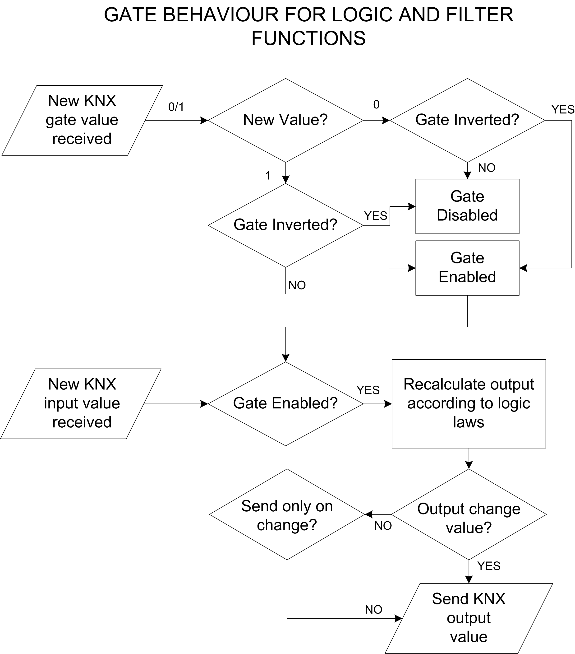
- Gate This property allows to establish through a ”gate” input (a value coming from a KNX group) if the operation can be executed.
If the property ”Gate” is ”Enabled”, the following properties will appear:- Inverted gate: This property states the value needed to enable the operation. If disabled, 1 enables and 0 disables it, if enabled, 0 enables and 1 disables it.
- Startup gate status: This property allows to specify the starting value of the KNX group corresponding to the gate.
- ’Read current value’: indicates to use the group current value as starting value.
- ’Wait for a new telegram’: indicates that the gate doesn’t take any value until the receiving of a telegram.
- ’0 until first telegram’: indicates that the gate takes value 0 until the receiving of a new telegram.
- ’1 until first telegram’: indicates that the gate takes value 1 until the receiving of a new telegram.
Gate group: This property allows to define the KNX group selected as a gateIn general, the gate behaviour is illustrated on the following flowchart. When the gate change its value and become enabled, it fires the logic calculation. The calculated output will be sent only if it match the “Output sending behaviour” (if “On result change” is chosen, the value will be sent only if different from the last sent).

In order to set up the list of the inputs of the combination, select the ”Inputs” property and click on the button displayed on the right.
In the displayed window, in order to add a new input, click and the ”Add” button below. An ”Input” object will be added to the list; select it and adjust the properties on the right.
- Input type This property allows to apply variations on the value coming from the KNX group. .
- ’Normal’: indicates that is not applied any adjustment.
- ’Inverted’: indicates that the value coming from the KNX group is denied so 1 becomes 0 and vice versa.
- ’Always 0’: indicates that the input value is always 0 independently from the value of the KNX group.
- ’Always 1’: indicates that the input value is always 1 independently from the value of the KNX group.
Value at startup This property indicates the value taken by the input at the launch.- ’Read current value’: indicates that the input starting value is equivalent to the value of the KNX group.
- ’Wait for a new telegram’: indicates that the input doesn’t take any value until the receiving of a new telegram.
- ’0 until first telegram’: indicates that the input takes value 0 until the receiving of the first telegram.
- ’1 until first telegram’: indicates that the input takes value 1 until the receiving of the first telegram.
KNX group This property indicates the KNX group the input is associated to.
Filter

The ’Filter’ object allows to perform operations on the value of an input KNX group and to send the result with an optional delay to an output KNX group. To set up the ”Filter” object, select from the system tree and adjust the properties displayed in the grid below.
- Filter type This property indicates the value assigned to the output depending on the input value.
- ’1 → - / 0 → - (disabled)’ indicates that no values are assigned to the output.
- (’1 → - / 0 → 0’) if input is equal to 1, no value assigned to the output. If input is equal to 0, 0 will be sent to the output.
- ’1 → - / 0 → 1’ if input is equal to 1, no value sent to the output. If input is 0, 1 is sent to the output
- ’1 → - / 0 → Toggle’ if input is equal to 1, no value will be sent to the output. If input is equal to 0, the output will toggle.
- ’1 → 0 / 0 → -’ If input is 1, output will be set to 0. If input is 0, no value will be sent to the output.
- ’1 → 0 / 0 → 1 (inversion)’ indicates that the input value is inverted and than sent to the output.
- ’1 → 1 / 0 → -’ indicates that if the input is 1, 1 is assigned to the output, if the input is 0, no values are assigned to the output.
- ’1 → 1 / 0 → 0 (pass all)’ indicates that both of the input values are sent to the output.
- ’1 → Toggle / 0 → -’: indicates that if the input is 1 the output value is inverted, if the input is 0 no values are assigned to the output.
- ’1 → Toggle / 0 → Toggle’ for every input value (both 0 or 1), the output will toggle.
Input group This property represents the KNX group of the input value.Delay This property indicates if is necessary to wait for a time interval before sending the output value to the KNX group.- ’Do not use’: disables the property so no delays are applied .
- ’Use if input is 1’: applies the delay only if the input is 1.
- ’Use if input is 0’: applies the delay only if the input is 0.
- ’Use always’: applies the delay for any input value.
If the property ”Delay” is not set to ”Do not use”, the following properties will appear:- Delay base time: This property indicates the measurement unit of the time interval of the delay.
- Delay factor: This property indicates the value of the time interval of the delay.
Output group This property represents the KNX group of the output value.Output sending behavior This property indicates when the result of the output operation has to be sent.- ’On result change’: indicates that the value is sent only when the result of the operation is different from the previous one.
- ’When a new input telegram is received’: indicates that the value is sent whenever the server receives a telegram from on of the KNX groups specified in the inputs.
Gate This property enables or disables the operation. See System - Combination .Multiplexer

This object, given an input and two outputs, allows to choose, through a control bit, the output which the input value has to be assigned to.
In order to set up the ’Multiplexer’ object, select it in the system tree and adjust the properties displayed in the grid below.
- Group input This property represents the KNX group of the input value.
- Input type This property indicates the type of data that has to be read on the input group.
- Group output A This property represent the KNX group of the output A.
- Group output B This property represent the KNX group of the output B.
- Control group This represents the KNX group of the control bit that decides the output which the input has to be assigned to.
- Type for 0 This property indicate which action has to be executed when the control bit is 0.
- Type for 1 This property indicate which action has to be executed when the control bit is 1. For properties ”Type for 0” and ”Type for 1” are available the following options:
- ’No transmission’: indicates that the input is not assigned to any output.
- ’From input to output A’: indicates that the input is assigned to output A.
- ’From input to output B’: indicates that the input is assigned to output B.
- ’From input to both output’: indicates that the input is assigned to output A and to output B.
Startup value This property indicates which starting value is taken by the control bit at server launching.- ’Read current value’: indicates that the control bit starting value is equivalent to the value of the KNX group.
- ’Wait for a new telegram’: indicates that the control bit doesn’t take any value until the receiving of a new telegram.
- ’0 until first telegram’: indicates that the control bit takes value 0 until the receiving of the first telegram.
- ’1 until first telegram’: indicates that the control bit takes value 1 until the receiving of the first telegram.
Gate This property enables or disables the operation. See System - Combination .Logic Matrix

This object, given n inputs and n outputs, selects an input with a 1 byte selector and sends it to an output chosen with a 1 byte selector.
- Data type KNX telegram type of input and output groups.
- Inputs List of all the inputs KNX groups.
- Outputs List of all the outputs KNX groups.
- Input control value group KNX group address of the value used to select the input (1 byte).
- Default input Input selected by default (default control value).
- Output control value group KNX group address of the value used to select the output (1 byte).
- Default output control value Default output control value (1 byte, 0-255).
- Update for every input control tel. If enabled, outputs will be updated for every received telegram to the input control (selection) group. If disabled, outputs will be refreshed only when a new telegram on the selected input is received or (if enabled) when a telegram on the output control group is received.
- Update for every output control tel. If enabled, outputs will be updated for every received telegram to the output control (selection) group. If disabled, outputs will be refreshed only when a new telegram on the selected input is received or (if enabled) when a telegram on the input control group is received.
- Gate This property enables or disables the operation. See System - Combination .
Click on the button displayed on the right to open inputs editor window, click on ”Add” and then adjust the properties in the grid:
- Label Name of the input.
- Control value Value assumed by the Input control value to select this input.
- Value at startup Value to assign at input during startup.
- KNX group KNX group of the input (it must follow the Data type property).
Click on the button displayed on the right to open outputs editor window, click on ”Add” and then adjust the properties in the grid:
- Label Name of the output.
- Control value Value assumed by the Output control value to select this output.
- KNX group KNX group of the output (it must follow the Data type property).
Linear combination

This object allows to calculate weighted sums between the bit values of specific input KNX groups and to assign the result expressed in bytes to an output KNX group. Therefore, the output value is:
C = p1 . v1 + p2 . v2 + … + pk . vk
where p1 is the load (from 0 to 255) associated to the addend v1 that is the value 0 or 1 coming from the input KNX group. It’s particularly useful in case it’s requested to modulate a KNX command through a byte because it allows to associate a different weight to each addend.
In order to set up the ’Linear combination’ object, select it in the system tree and adjust the properties displayed in the grid below.
- Addends This property represents the list of values coming from different KNX groups that will be summed .
- Output sending behavior This property indicates when the result of output operation has to be sent.
- ’On result change’: indicates that the value is sent only when the result of the operation is different from the previous one.
- ’When a new input telegram is received’: indicates that the result is sent whenever the server receives a telegram from one of the KNX groups specified in the inputs.
Output group This property represents the KNX group which the sum will be assigned to.In order to set up the addends of the sum, select the property ’Addends’ and click on the button displayed on the right. In the displayed window, to add a new addend, click on the ’Add’ button below. An object ’Addend’ is added to the list, select it and adjust the properties on the right.
- Name Label of text that identify the input.
- Load This property associates a load (a multiplier) to the value of the KNX group corresponding to the addend. Doing so it’s possible to obtain a weighted sum between the addends and to associate an importance level to each KNX group.
- KNX group This property represents the KNX group which the value of the addend can be picked from.
Logic Module

This object represents a collection of block diagrams which allows you to build complex logics with a graphical editor. For more informations please refer to the Logic Module section.
- Schemes List of schemes, each element represents a fully working block diagram.
Complex Maths Expressions
The ”Complex maths expressions” object represents a collection of logical and arithmetical operations that can be written to elaborate values coming from different KNX groups. It’s possible to write expressions for the calculation of sums, balances, means, absolute values and analogical values, such as temperature and consumption, coming from KNX commands.
To write an expression, add the ”Complex maths expressions” object, select it and adjust the properties displayed in the grid below.
- Expression This property represents the list of defined maths expressions, please refer to the following paragraph.
Click on the ”Add” button in the displayed window. An ”Expression” object is added to the list, select it and adjust the properties on the right.
- Expression This property contains the syntax of the maths expression. Select it and click on the button displayed on the right. In the displayed window, type the text of the expression in the text box above and click on the ”Check” button below. The check is used to test the expression accuracy and to create the variables. Each variable represents an input that is a value of a KNX group.
Please note that many math functions are included. The following list includes the available functions:- abs Calculates the absolute value of a numeric parameter
- avg Calculates the average of a list of numbers. The list items must be convertible to double
- between Indicates if a value is between the other values. Please note that the comparison is inclusive
- cos Calculates the cosine of a number
- iif Performs an if-else-end
- isbitclear Verify if a bit is clear into an integer number
- isbitset Verify if a bit is set into an integer number
- isfalseornull Indicates if the parameter has the value false or is null
- isnullorempty Indicates if the parameter is null or empty
- istrueornull Indicates if the parameter has the value true or is null
- mid Calculates the median for a list of numbers
- not Performs a NOT on a boolean parameter
- numericmax Finds the maximum numeric value in a list
- numericmin Finds the minimum numeric value in a list
- random Return a random number comprised between indicated limits
- regulator Implements regulation of an output provided a setpoint and an actual value. The result can be inverted with an additional variable. Implements symmetric hysteresis.
During non inverted mode result will be 0 when actual value is less than setpoint value minus hysteresis and 1 when higher than setpoint plus hysteresis.
In inverted mode the result will be inverted. Can be used as thermostat with heating/cooling functionality. Refer to manual for more details. - round Rounds a numeric value to the number of decimal places
- sin Calculates the sin of a number
- sqrt Calculates the square root of a number
Alternatively, to view a complete list of available functions and their syntax click on the “?” button.
Output sending behavior This property indicates when the result of the output operation has to be sent.- ”On result change” indicates that the value is sent only when the result of the operation is different from the previous one.
- ”When a new input telegram is received” indicates that the result is sent whenever the server receives a new telegram from one of the KNX groups specified in the inputs.
Output group This property indicates which KNX group the result of the operation has to be assigned to.Type Type of number to extract from the value read from bus.To enter the math expression click on the button on the right of the property “Expression” in the “Expressions Editor” window, which contains the list of all the expressions. In the single “Expression Editor” window the math expression can be directly added, with the desired variable names.
Clicking the “Check” button variables are generated and for each variable following properties can be set.- Value at startup This property allows to specify the starting value of the variable when the server is launched.
- ”Read current value” takes as starting value the value of the associated KNX group.
- ”Wait for a new telegram” doesn’t assign any value to the input until the receiving of a new telegram from the associated KNX group.
- ”0 until first telegram” indicates that the input takes value 0 until the receiving of the first telegram from the associated KNX group.
- ”1 until first telegram” indicates that the input takes value 1 until the receiving of the first telegram from the associated KNX group.
KNX group This property represents the KNX group associated to the variable.Type Type of number to extract from the value read from the bus.Trigger computation This property is particularly useful in case the same KNX group is used for both the result and another variable: in those situations loop may occurs. Setting this property to “Disabled” store the value for next computations and avoids loops. If the property is set to “Enabled”, the incoming values will trigger the computation of the expression and the sending of the new value.The change of the expression doesn’t involve of the previously set properties of the variables. Renaming a variable involves the cancellation of the old one and the creation of a new one: the new variable doesn’t acquire the properties of the old one.
Whenever the text of the expression is changed, click on the ”Check” button before clicking on ”Ok”. Not doing so, the variables do not generate and the expression is not saved.
The expression can contain mathematical operators such as +, -, *, /, > (greater-than), < (less-than), = (equal), := (assignment), <> (different) and logical operators such as ”AND” and ”OR”. Decimals have to be expressed with ”.” symbol, for example 0.9, 1.5, 20.05. Each line have to end with ”;” symbol. Is possible to include mathematical functions such as mean, absolute value and rounding. For a complete list of functions with related syntax, click on the ”?” button below.
Importing and exporting Expressions
This feature allows to export a list of expressions previously created in a project and import it in another project.
To export the expressions list, open the expressions list editor window by clicking on the button displayed on the right of the ”Expressions” property. Click on the ”Export” button and choose the path of the xml file that will be created, in this way the list of expressions will be saved outside the Configurator.
To import the expressions list in a project, open the expressions list editor window by clicking on the button displayed on the right of the ”Expressions” property. Click on the ”Import” button and select the xml file previously saved and click on OK button to confirm. A list of expressions will appear in the editor window.
KNX variables

This object represents a collection of values stored in the server and associated to a KNX group. Through these variables it is possible to store, for example, the results of mathematical or logical operations and make them available on KNX through a group address. It is possible to choose if the value will be stored on the server in a persistent way, which means that the value will be available also after the server reboot.
- Variables KNX variables to be used for computation or for storage.
- Trigger write from KNX Permits to force the server to send (write) the content of the KNX variables to the KNX bus after receipt of a KNX telegram with a defined value. When set to “Enabled” following properties will appear:
- Trigger KNX group: KNX group used to trigger the write of KNX variables to KNX bus.
- Trigger KNX value: Permits to choose the value that has to be sent to the trigger KNX group to invoke KNX variables write. There are three alternatives: “All values”, “Only 1”, “Only 0”.
Trigger write timebased Permits to force the server to send (write) the content of the KNX variables to the KNX bus basing on a timer with a defined interval. When set to “Enabled” following property will appear:- Trigger time interval: Time interval (in seconds) after which a new KNX variable write to the KNX bus is invoked.
In order to add a variable the variable editor must be opened. Click on the ”Add” button to define following properties:
- KNX group: KNX group associated to the variable; through this group address it is possible to read the value or to set a new value.
- Type: DTP of the variable value.
- Store Value: Enable or disable the storage of the variable value. If enabled the variable value will be stored on the server and will persists on reboot. If disabled, the variable value will be lost after the server reboots.
- Readable from bus: The value can be read from the KNX bus
- Read at startup: When the device starts up, it will read the value from the bus to initialize its state.
- Write at startup: At startup, the device will write its value to the bus to inform other devices of its current state.
- Write sequence: Choose when the server will be write the information on the bus, before the read or after
- Write on time: Write back to the bus the last received value following the general scheduled write.
Database

This object represents a service to store data coming from the plant on a cloud database. All these data will be accessible through the Chart interface object.
This objects works correctly only if the ThinKnxCloud service is enabled and configured!
- Values collection List of values to store in the cloud database.
A database variable is an object which represent the value to store in the database. Clicking on the button on the right of the Values Collection property. Add a new value with the Add button and edit its properties to configure the saving modalities:
- Name Name associated to the value.
- Unit of measure Unit of measure associated to the value in the database (optional).
- Multiplying factor Conversion factor applied to the value before storing it in the database.
- Source Bus type of the value to read, the possible options are KNX and Modbus.
If Source is set to KNX, the following properties will be displayed:- Type: Data type of the value read from KNX.
- Group address: Value’s KNX group address. If Source is set to Modbus, the following properties will be displayed:
- Type: Data type of the value read from KNX.
- Modbus gateway: Modbus gateway that contains the datapoint to read.
- Modbus datapoint: Value’s Modbus datapoint.
The following properties must be configured to define storing rules in the database:
Store trigger Policy used by the server to pick the values from the bus and store them on the cloud.- On new value reception: The server will send the value to the cloud every time it receives a telegram from KNX. This option is useful when the user wants a precise representation of the data during the day, for example, for power consumption. This option is although space consuming so we recommend to use it carefully.
- After a fixed time interval: The server will read the value from KNX after a determined time interval and store it on the cloud. This option can be used, for example, to read temperatures and all that values that doesn’t change that much during the day.
- On over-threshold change: The server will store locally the last value received from KNX and it will compare it with the latest incoming telegram, if the difference between the two values overcross a predefined threshold it will store the new value on the cloud. The threshold represents the ratio between the gap of the two values and the previously stored value. This option is useful because allows the user to keep trace only of the significant changes of the value during the day.
- On over-threshold change and after time: This option combines the advantages of both previously explained techniques. Data will be stored when over-threshold change occurs and, in any case, after a fixed time interval.
If the Store trigger property is set to ”After a fixed time interval”, the following property will be displayed:
Store time interval Time interval to wait before the server sends the value to the database.
If the Store trigger property is set to ”On over-threshold change”, the following property will be displayed:Change percentage Minimum change percentage required to store a new value on database. To be stored, the new value has to differ more than this percentage from the previous value.
If the Store trigger property is set to ”On over-threshold change and after time”, both Change percentage and Store time interval property are displayed.Value to store Math elaborations applied the data picked with the Store Trigger policy.- Last received value: The value will be sent to the cloud without additional elaborations.
- Math derivative of values: The server will compute the derivative of the values coming from KNX telegrams in the interval after the last value sent. If the Store Trigger is set to ”On new value reception”, the derivative will be computed between the last value stored and the new one while, if the Store Trigger is set to ”After a fixed time interval”, the derivative will consider all the telegrams received during the time interval. This elaboration can be useful, for example, when the server reads the value of energy from KNX and the user wants to store the power.
- Math integral of values: The server will compute the integral of the values as explained in the previous option. This laboration can be useful when the server reads the value of power from KNX and the user wants to store the energy.
- Simple mean of values: The server will compute a simple mean of the values as explained above.
- Weighted mean of values: The server will compute a weighted mean of the values as explained above.
To avoid an exponential growth of the data contained in the database, it is possible to apply some filter to old data:
After 1 day filter Filter to be applied to data older than one day.- Do not filter: No filtering applied to data.
- Discard all values: All the data will be deleted.
- Simple mean on new interval: All the data older than one day will be grouped following a predefined time interval, the data inside each group will be discarded and the simple mean of the group will be stored in database.
- Weighted mean on new interval: All the data older than one day will be grouped following a predefined time interval, the data inside each group will be discarded and the weighted mean of the group will be stored in database.
If the selected filter is a mean, the following property will be displayed:
Interval for 1 day filter Time interval applied to the filter.After 1 week filter Filter to be applied to data older than one week. Please refer to the property above for the available options.After 1 month filter Filter to be applied to data older than one month. Please refer to the property above for the available options.After 6 months filter Filter to be applied to data older than six months. Please refer to the property above for the available options.After 1 year filter Filter to be applied to data older than one year. Please refer to the property above for the available options.Since the quantity of data storable for each server in the cloud database is limited, it is highly recommended to use the filter policies.
Log Manager
This object represents a service for storing connection data from users or from the cloud. It categorizes them and checks actions on specific data related to system, KNX, or Modbus protocols.
- Label Text label to identify the object
- Log connection events
- Log cloud event
- categories
- sources
Reports and Gateways
Report

This object defines a values collection to be saved in the internal memory according to time intervals defined by the installer. This values are sent via mail and optionally organised in charts.
- Recipients List of possible recipients.
- Values List of configured values.
- Title Report title.
- Text Email message text.
- Subject Subject of the email containing the report.
- Html If enabled, report will be sent as a html file (readable by a standard web browser), otherwise it will be sent as a text file.
- Create chart If enabled, a chart representing data analysed by the report, is attached to the email.
- Store interval The system stores a data recording of the pre-set value after this pre-set timespan.
- Read interval The system reads the recorded values after this pre-set timespan.
- Use default SMTP SMTP server determines the email sender address; if enabled, email messages are sent from the default SMTP; if not, the following property is displayed:
- Email Account Select the ”Email account” item from the list. Please refer to the dedicated section above.
it is always advised to disable the Default SMTP and create an Email Account object in System to be used here. See section Email Account for more information.
Click on the button displayed on the right to open recipients editor window, click on ”Add” and then adjust the properties in the grid:
- Email address Recipient’s address.
- Added subject Text to be added to the main report subject for this specific user.
- Added text Text to be added to the main report text for this specific user.
- Sending interval Time interval between two consecutive report sending.
Click on the button displayed on the right to open values editor window, click on ”Add” and then adjust the properties in the grid:
- Force read If enabled, the value is read before storage.
- Store Trigger Trigger used to store value. Using fixed interval a new value will be stored after interval is elapsed. Using change percentage method instead a new value will be stored. If it differs more than a defined amount from the previous value.
- Unit of measure Measuring unit associated to the value.
- Multiplying factor The recorded value is obtained by multiplying the read value with this factor.
- Type Type of KNX value.
- Source KNX or Modbus.
If KNX option is selected the following property will be displayed:- KNX group KNX group address of the value to be read.
If Modbus option is selected, the following properties will be displayed: - Gateway Modbus gateway.
- Modbus datapoint Datapoint which the server reads the value from.
Hue gateway

This object allows the server to control Philips Hue lamps. It is possible manage shades of white or all the colours in the spectrum from the configurator.
- IP address Bridge IP address.
- MAC address MAC address of the bridge. It is imported automatically.
- Controlled elements List of configured Hue elements.
Clicking on the button on the right of the IP address property or MAC address it is possible to open the Hue Bridge Finder window. In this window, the configurator searches for Hue Bridges connected to the local network and displays them in a list. Every bridge can be ”Authorized” or ”Not Authorized”:
- Authorized: the connection to the Configurator isn’t the first one and it was already authorized.
- Not Authorized: the connection to the Configurator isn’t authorized (it usually happens the first time the Configurator detect the bridge). To authorize the connection, click the ”Register bridge” button and follow the procedure explained in the new window. If this procedure has a positive ending, the bridge will switch to ”Authorized”.
Clicking the ”Select bridge” button the selected bridge is associated to the Hue gateway object.
Reading Hue Bridge configuration and creating Hue Lights Groups
In the ”Hue Bridge Finder”, under each Authorized bridge node, there is a list of all the lights and groups configured in the Bridge. With a right click on the bridge is possible turn on or turn off all the lights, refresh the properties read from the bridge and create a new group of lights. Selecting a lamp node, in the property grid on the right, the properties configured in the bridge are displayed:
- ID ID associated to the lamp in the Hue Bridge.
- Name Name associated to the lamp in the Hue Bridge, it is possible to edit this property and the changes will apply also to the Hue Bridge.
- State Current status of the Hue lamp (on/off/dimming).
- Type Hue lamp type (colored, white, etc.).
- Model ID Hue lamp model code.
- Software version Hue lamp firmware version.
- Unique ID Unique ID associated to the lamp in the Hue Bridge.
Every Hue lamp node has a child node, which is the lamp status node. By selecting it a list of editable properties will be displayed:
- Turned ON If enabled, the Hue lamp switches to the ON state. it's useful to try the hue lamp.
- Hue Current hue value.
- Brightness Current brightness value.
- Saturation Current saturation value.
- Color Temperature Current color temperature.
- Effect Current color effect.
- Alert ???
- Color Selected color, by changing this property the properties above will assume different values.
After editing these properties, to save them in the Hue Bridge, click the ”Save Properties” button.
The Configurator allows to create Hue Groups directly from the ”Hue Bridge Finder” window: right click on the Bridge node and select ”Create new lights group” in the menu that appears. This action adds a child node to the Groups node, selecting the group properties will be displayed:
- ID ID associated to the group in the Hue Bridge.
- Name Name associated to the group in the Hue Bridge, it is possible to edit this property and the changes will apply also to the Hue Bridge.
- Type Property indicating the type of Hue element (always LightGroup).
- Model ID Model Hue element.
- Lights List of Hue lamps which will be part of the group.
Every Hue group node has a child node, which is the group status node. The properties of the status node are the same of the single Hue lamp but they apply to all the lamps of the group.
All the properties listed in the ”Hue Bridge Finder” window are used to test the Hue Bridge configuration (or edit it) but they don’t represent the real configuration needed by ThinKnx server to control the lights. The real configuration is made by adding a controlled element. Please refer to the chapter below.
Clicking on the right button of the Controlled elements property, a window will be displayed. Click on the ”Add” button, select the added object and adjust its properties:
- Element name Name of the Hue element.
- Element type Type of the Hue element to control, it can be a single light or a group of lights.
If the ”Element type” property is set to Light, the following properties will be displayed:- Hue light: Hue light previously detected with the Hue Bridge Finder tool.
- Light ID: Identifier used to match the Hue light in the Hue Bridge.
- Light unique identifier: Unique identifier used to match the Hue Light in the Hue Bridge.
If the ”Element type” property is set to Group, the following properties will be displayed: - Hue group: Hue group previously configured with the Hue Bridge Finder tool.
- Group ID: Identifier used to match the Hue group in the Hue Bridge.
Both lights and groups have the following properties:
Simulate type Type of feature to control with ThinKnx server: Dimmer colored, Dimmer white, ON/OFF colored, ON/OFF white and RGB.
If the Simulate type is ”Dimmer colored” or ”ON/OFF colored” the following property will be displayed:- Start color: Base color for the element.
If the Simulate type is ”Dimmer white” or ”ON/OFF white” the following property will be displayed: - Color temperature: Base color temperature for the element (warm or cold).
If the Simulate type is ”Dimmer colored”, ”ON/OFF colored”, ”Dimmer white” or ”ON/OFF white” the following property will be displayed: - Force color: If enabled, the chosen color/color temperature will be forced every time a command is sent. If disabled, the chosen color/color temperature are sent to the element just when the server start, every other command will not send the color again.
Every Hue element can be controlled from KNX and send feedback to KNX through the properties:
KNX gateway If enabled it will be possible to control the current element directly from KNX and receive feedbacks into KNX.KNX switch group KNX group (1bit DPT1) to command (turn off and on) the current element.KNX switch feedback group KNX group (1bit DPT1) to notify the status of the current element (1 = ON, 0 = OFF).
If the Simulate type is ”Dimmer colored” or ”Dimmer white” the following property will be displayed:- KNX dimming group: KNX group (4bit DPT3) for dimming up and down the current element.
Commands sent to the object and recallable from other objects:
This command allows to start turn on or off the Hue element.
- Value Write 1 to turn on, and 0 to turn off.
This command allows to set the desired value for the dimmer through a single parameter which can assume a value between 0 and 255.
- Value can be between 0 and 255.
Set the element color temperature (white)
This command allows to set the element color temperature.
- Value Can be between 0 and 255, where 0 corresponds to Cold White (6500 K) and 255 correspond to Warm White (2000 K).
Set the element RGB color through the definition of three parameters for Red, Green and Blue. Each color can assume a value between 0 and 255.
- Red Value value between 0 and 255.
- Green Value value between 0 and 255.
- Blue Value value between 0 and 255.
Load control

This server service reads the electrical energy consumption in a specific plant point from KNX group. Basing on thresholds previously set by the installer, the server can disconnect the load for a predetermined time interval or notify the user.
- Type Value type.
- Maximum power Maximum contractual power supported by the entire plant expressed in Watt.
- Warning threshold When this adjustable threshold (expressed in Watt) is reached by the plant, a warning is sent to the pre-set KNX group.
- Power value group KNX group which the object reads the values from.
- KNX alert power KNX group to change the alert power level. The datatype used is the same selected for actual power KNX group
- KNX max power KNX group to change the maximum power level. The datatype used is the same selected for actual power KNX group
- Warning group KNX group which the system sends the 1 value to (f.e expressed with an alert message)(1bit).
- Reconnection time After this pre-set time span, configured loads are automatically reconnected to the plant.
- Disconnection time After this system continually reports the warning threshold value for the pre-set timespan, configured loads are automatically disconnected from the system.
- Time between loads disconnection If more than one load is configured, they will be disconnected from the system one by one, basing on this pre-set timespan.
- Loads Loads related to the plant portion controlled by this object; when the warning threshold is reached, they are automatically disconnected from the system. If no load is configured, the system will only make a data reading and send a warning message if the warning group has been previously set.
Click on the button displayed on the right to open the loads editor window, click on ”Add” and adjust the properties in the grid:
- Load Name Label of text to identify the load
- Reversed Functioning Enable this option if the load is connected ot a normally closed actuator channel and you need to sen 0 to power and 1 to turnoff. Also Feedback is considered inverted.
- Load KNX group KNX group that control the on/off commands.
- Load KNX status group KNX group feedback.
Gateway Modbus

This object allows to communicate with Modbus devices when Thinknx server is used as a Modbus Master.
A Modbus Master is a device that handles the entire communication with one or more slaves, whilst the Slave is completely passive and just replies to polls/commands from the Master. A Modbus Slave cannot initiate communication, either to the Master or to other Slaves.
Do not confuse the concept of Master-Slave with Client-Server. While Master-Slave is explained from a Modbus perspective, the Client-Server is interpreted from a network perspective when using TCP media. A Modbus Master connecting to a a Modbus Slave is considered a “client” to the slave device which is the “server”.
- Communication Type Define the method and mean of communication. Serial over TCP is used when a Serial Server is used.
- If in the property ”Communication Type” is selected the setting ”Modbus Serial”, the following properties will appear:
- Port Number: Serial port number that changes depending on the server used. Click here to get the correct port number.
- Baud Rate: Modbus Baud Rate
- Data Length: Number of bits for data
- Parity: Parity check modality
- Stop Bits: Number of stop bits.
- Comm. timings: Serial timings to optimize communication over the RS485 bus. It depends on bus adapter, slave devices timings etc.
If in the property ”Communication Type” is selected the setting ”Modbus Serial on TCP” or ”Modbus TCP”, the following properties will appear:- IP Address: IP address of the device or of the serial adapter
- IP Port IP: port used when the device listen for communication (502 is a standard for TCP protocol).
- Datapoints Data points collection
- Poll Interval Pause between two consecutive polling sequences [ms]
- Write refresh interval Pause between two consecutive write sequences[ms]. It permits to rewrite datapoints at a certain rate and it is valid only for the enabled datapoint.
For each Datapoint created, the below parameters are available:
- Name datapoint label
- Slave Address Physical slave address of the device where the data is configured.
- Data address Data address where the data is stored.
- Data type type of data to read/write.
- Read Function Modbus standard function that has to be used to read the value (consult device manual).
- Write Function Modbus standard function that has to be used to write the value (consult device manual).
- Bit number number of bits inside the data that represent the value.
- Conversion factor conversion factor to multiply the read raw value.
- Reuse If several bits need to be read from the same address X, this parameter will help improve the reading speed by avoiding polling the slave every single time to read 1 different bit from the same address. For example, if multiple datapoints have been created for the same address, each datapoint with a different bit number to read from (typically each bit is a different toggle status), then only the first datapoint will have the “Reuse” parameter set to “False”, while the other datapoints will have the “Reuse” parameter set to “True”. The driver will read the 2 bytes from address X only the first time and will extract all the subsequent bits from this read value to populate the other datapoints.
- Force rewrite If enabled, permits to refresh (re-write) the last written value to the slave cyclically, based on the interval configured in “Write Refresh Interval” in the main settings.
- Gateway KNX if enabled, allows to read/write Modbus values from KNX system.
- KNX data type EIS data type that has to be written into the KNX group.
- KNX group from Modbus KNX group to read feedback from Modbus. Values are read from Modbus slaves and sent to this KNX group address.
- Send if change if enabled, sends value on KNX bus just in case Modbus value changes.
- Enable KNX to Modbus By default, the KNX gateway will read data from Modbus and send feedback to KNX. If bidirectional communication is needed, enable this parameter.
- KNX group to Modbus KNX group to receive value and write to Modbus. Values are received from this KNX group address and are written to Modbus.
Commands sent to the object and recallable from other objects:
Send Modbus value with function 5
This function is used to send a value to a Modbus device supporting function 5, known as “write single coil”.
- Modbus address Modbus address.
- Coil Address Discrete output address (coils are 1-bit registers).
- Value could be 1 or 0.
Send Modbus value with function 6
This function is used to send a value to a Modbus device supporting function 6, known as “Write Single Holding Register”.
- Modbus Address Modbus address.
- Register Address Slave register.
- Value value to write.
- N.Byte Number of bytes.
Send Modbus value with function 16
This function is used to send a value to a Modbus device supporting function 16, known as “Write Multiple Holding Registers”.
- Modbus Address Modbus address.
- First Register Address Slave register.
- Value value to write.
- N.Byte Number of bytes.
Send Modbus value with function 22
This function is used to send a value to a Modbus device supporting function 22. The function can be used to set or clear individual bits in the register.
- Modbus Address Modbus address.
- Register Address Slave register.
- Value value to write.
- Selected bits mask mask value of the selected bits to be changed.
Gateway Modbus Slave
It allows to communicate with Modbus slave devices when Thinknx server is used as Slave Gateway.
- Communication Type Define the method and mean of communication. Serial over TCP is used when a Serial Server is used.
- If in the property ”Communication Type” is selected the setting ”Modbus Serial”, the following properties will appear:
- Port Number: Serial port number that changes depending on the server used. Click here to get the correct port number.
- Baud Rate: Modbus Baud Rate
- Data Length: Number of bits for data
- Parity: Parity check modality
- Stop Bits: Number of stop bits.
- Custom Timing: if enabled, it allows to change the waiting times below:
- waiting time after enabling RTS before the writing begins.
- waiting time after writing before disabling RTS.
- waiting time after disabling RTS before the reading begins.
If in the property ”Communication Type” is selected the setting ”Modbus Serial on TCP” or ”Modbus TCP”, the following properties will appear:- IP Address: IP address of the device or of the serial adapter
- IP Port IP: port used when the device listen for communication (502 is a standard for TCP protocol).
- Device Address Address of the slave device (1byte) to be used on the bus for identification.
- Modbus Type variant of the Modbus protocol to use for communication. Select between RTU (mostly used) and ASCII.
- Datapoints Datapoints collection
For each datapoint created, the below parameters are available:
- Name datapoint label
- Data address Data address where the data is stored.
- Data type type of data to read/write.
- Read Function Modbus standard function that has to be used to read the value (consult device manual).
- Write Function Modbus standard function that has to be used to write the value (consult device manual).
- Bit number number of bits inside the data that represent the value.
- Conversion factor conversion factor to multiply the read raw value.
- KNX group KNX group to send value to.
- KNX data type EIS data type that has to be written into the KNX group.
- Send if change if enabled, sends value to KNX bus just in case Modbus value changes.

Thinknx Server as a Modbus Gateway to Other Systems

Case Study: Modbus Gateway
Gateway MyHome

It allows the bidirectional connection of MyHome BTicino plants to KNX plants. Through easy-to-fit tables it is possible to set matching among the messages coming from the two systems. In order to be able to communicate with MyHome system, a MyHome Ethernet gateway is needed, similar to BT-F454 web server that supports the Open Web Net protocol.
- IP Address IP address of the device or of the serial server
- Port Number Serial port number that changes depending on the server used. Click here to get the correct port number.
- Lights Collection of lights.
- Automation Collection of shutters.
- Heating Collection of heating and cooling elements.
Commands sent to the object and recallable from other objects:
This command allows launching of a scenario configured on the MyHome system.
- Scenario Number as configured in MyHome.
- Control Panel
- Interface (I)
Lights: point to point control ON/OFF
This command allows to send an ON or OFF command to one lighting point.
- Room (A) as configured in MyHome.
- Light Point (PL)
- Interface (I)
- ON/OFF type 0 to turn off and 1 to turn on.
Lights: point to point control DIMMER
This command allows to send a dimming value to one dimmer.
- Room (A) as configured in MyHome.
- Light Point (PL)
- Interface (I)
- Dimmer Level type a value between 0 and 255 for dimmer's level.
Lights: point to point control TIMED
This command allows to send an ON value duration for one light point.
- Room (A) as configured in MyHome.
- Light Point (PL)
- Interface (I)
- ON timed for (min) the values can be 0.5, 1, 2, 3, 4,5, or 15 min.
Lights: control for room ON/OFF
This command allows to send an ON or OFF command to an entire room.
- Room (A) as configured in MyHome.
- Interface (I)
- ON/OFF type 0 to turn off and 1 to turn on.
Lights: control for room TIMED
This command allows to send an ON value duration for an entire room.
- Room (A) as configured in MyHome.
- Interface (I)
- ON timed for (min) the values can be 0.5, 1, 2, 3, 4,5, or 15 min.
Lights: control for group ON/OFF
This command allows to send an ON or OFF command to a group of lighting points.
- Group as configured in MyHome.
- Interface (I)
- ON/OFF type 0 to turn off and 1 to turn on.
Lights: control for group DIMMER
This command allows to send a dimming value to a group of lighting points.
- Group as configured in MyHome.
- Interface (I)
- Dimmer Level type a value between 0 and 255 for dimmer's level.
Lights: control for group TIMED
This command allows to send an ON value duration for a group of lighting points.
- Group as configured in MyHome.
- Interface (I)
- ON timed for (min) the values can be 0.5, 1, 2, 3, 4,5, or 15 min.
Lights: general control ON/OFF
This command allows to send an ON or OFF command to all lighting points.
- ON/OFF type 0 to turn off and 1 to turn on.
Lights: general control DIMMER
This command allows to send a dimming value to all lighting points.
- Dimmer Level type a value between 0 and 255 for dimmer's level.
This command allows to send an ON value duration for all lighting points.
- ON timed for (min) the values can be 0.5, 1, 2, 3, 4,5, or 15 min.
Automation: point to point control
This command allows to control a single shutter by sending Up, Down or Stop.
- Room (A) as configured in MyHome.
- Automation Point (PL)
- Interface (I)
- Stop/Up/Down Stop=0, Up=1, Down=2.
This command allows to control a group of shutters by sending Up, Down or Stop.
- Group as configured in MyHome.
- Interface (I)
- Stop/Up/Down Stop=0, Up=1, Down=2.
This command allows to control all shutters in a single room.
- Room as configured in MyHome.
- Interface (I)
- Stop/Up/Down Stop=0, Up=1, Down=2.
This command allows to control all shutters.
- Stop/Up/Down Stop=0, Up=1, Down=2.
This command allows to change the setpoint in a zone.
- Zone (ZA, ZB) as configured in MyHome.
- Temperature type the value of the temperature in °C.
Temperature Control: enable or disable
This command allows to enable/disable the thermostat.
- Zone (ZA, ZB) as configured in MyHome.
- Enable or disable type 1 to enable and 0 to disable.
This command allows to control the volume of a speaker.
- Room (A) as configured in MyHome.
- Loudspeaker (PF)
- Volume the number must be between 0 and 255.
++++Sound: control a speaker ON/OFF
This command allows to turn a speaker on or off.
- Room (A) as configured in MyHome.
- Loudspeaker (PF)
- ON/OFF insert 1 to turn on and 0 to turn off.
Z-Wave Controller

It allows to integrate Z-Wave devices. Without any gateway, the result is a reliable and easy-to-use system with a bidirectional connection between Z-Wave and other standards such as KNX.
For a full list of all the compatible Z-wave devices with Thinknx server, visit our database.
- Use internal controller If enable, it will be used the server internal Z-Wave controller. If disabled it will be possible to use an external Z-Wave controller. This option is only used during configuration phase. If disabled, following properties will appear:
- IP address: IP address of the external Z-Wave controller
- Password: Server password (of the web page) of the external Z-Wave controller
Nodes Collection of the Z-Wave nodes registered inside the controllerPing Nodes If enabled, all the nodes will be pinged every minute. In this way a failed node will be promptly reported.Auto-Healing Healing is a procedure to reconstruct network in case of nodes not reachable or moved. If Auto-Healing is enabled, it will be performed in case of a node is marked as failed. Healing will be performed during right-time at 2.00 AM.The Z-Wave license is mandatory to control Z-Wave devices. Login to the server web pages, open the Status page and verify that the Z-Wave license is enabled for the server:

Server Z-Wave license
To work, Z-Wave Controller requires the ThinKnx Z-Wave transceiver (USB dongle) provided together with the Z-Wave upgrade (license). After plugging the transceiver to the ThinKnx server, always perform a server soft-restart.
To configure the Z-Wave controller, the Configurator software needs a direct IP connection to the ThinKnx server, for this reason the properties “Password” and “Local IP address” of the System object must be filled with respectively the service user password and the local IP of ThinKnx server. For more details refer to System object.

Entering server info in configurator
To open the Z-Wave Controller window, in the “Z-Wave Controller” object property grid, open the “Nodes” editor. In the window that appears, check the little circle in bottom-left corner of the window: it is an indication of successful connection of Configurator and ThinKnx server, green means connection successful while red means connection failure. In case of red circle, check “Local IP address” and “Password” properties of System object as mentioned above.

Connection status
ThinKnx Z-Wave transceiver offers a factory reset procedure which allows to reset the Z-Wave Controller and thus remove all the nodes associated to the Controller. This procedure just resets the Controller, all the nodes will keep the association and need to be reset separately. To launch the factory reset, right click on the Controller node in the Nodes editor window and select the “Controller factory reset” menu item.
Managing Z-Wave nodes: acquisition, exclusion, parameters and associations
To display the list of Z-Wave nodes associated to the Controller, open the Z-Wave Controller window by clicking on the “Nodes” property editor. In the window that appears, all the Z-Wave nodes stored in the Configurator project will be listed in the treeview under the Controller treenode. Each node icon can be:
- Grey: the node has been previously associated to the Controller and it is saved in the Configurator project. The list of nodes stored in the project can be different to the list in the Controller, to download the list of Controller and to detect if the node is online or offline click on the “Read Nodes from controller” as shown below.

Reading nodes from controller
- Green: the node is associated to the Controller and is online (the Controller can reach it in the Z-Wave network)
- Red: the node has been previously associated to the Controller but at the moment is offline (the Controller can't reach it in the Z-Wave network).
This section described how to include Z-Wave modules using the ThinKnx server. As an example, a NETIChome Dimmer module will be used to show the procedure.

NETIChome Dimmer
Before starting please reset your Z-Wave module to factory settings (usually done by holding reset button for a few seconds)
According to its user manual, the NETIChome Dimmer is reset as shown below:

NETIChome Dimmer reset procedure
First of all, to include the node, the Controller must enable the Inclusion procedure: in the Z-Wave Controller window, right-click on the “Controller” treenode and select “Start node acquisition”. According to the instructions on the screen, start the inclusion procedure also on the Z-Wave module and if the inclusion is successful the message “Completed! New Node included and read” will appear.

Node acquisition

NETIChome Dimmer Module Inclusion procedure

Successful node acquisition
If the inclusion of the node has been successful, the node will be added to the treeview under the Controller node. As a double check of the successful inclusion, right-click on the node and select “Ping node”. If the ping is successful the node has been included properly, otherwise it is possible that the inclusion has not been completed properly. In this case, right-click on the node and select “Remove if failed”, reset the Z-Wave module and try again the inclusion.
To start the exclusion procedure, right-click on the Controller treenode in the Z-Wave Controller window and select “Start node exclusion”. According to the instructions on the screen, start the exclusion procedure also on the Z-Wave module and when the exclusion is completed, the message “Completed!” will appear.
Each Z-Wave module included can have some Parameters to edit its functioning
In the “Device parameter editor” window, depending on the device you are configuring, you will find different parameters that can be adjusted according to your needs.
As an example you can see a couple of parameters defined by NETIChome for their dimmer device:

NETIChome Dimmer Parameters
The association function “associates” two devices, enabling them to communicate directly without the need for controller. On the “Device association editor” window, you can set an association with other Z-Wave devices and define the type of association.
Velux Gateway
This gateway allows to communicate with the Velux KLF200 interface to control the nodes and groups configured on it, whether directly or through the KNX bus.
The web access credentials and SSID can be found on the back of the Velux unit as seen in the picture below:

Velux Credentials
From your PC, scan for available wifi networks, and connect to the Velux SSID found.
Open the browser and type the following link: http://klf200.velux. Use the credentials on the device to sign in.

Velux Web Access
Open the Interface Mode to scan and add your products.

Interface Mode

Product Search
For more information on how to setup the Velux interface, check out this video posted by Velux Commercial https://youtu.be/kVmqGOMKqoM
Network Setup
After logging into the interface, click on the gear button at the top right, and select “LAN”.

LAN Settings
Fill in your desired IP Address, Subnet mask, Default gateway (that fits to your LAN) or click on “Use DHCP”.
The important thing is to configure the Velux within the same LAN as the Thinknx server to ensure communication between both parties.
Add the Velux interface in System and configure the correct IP address and port to communicate with the Velux interface.
The below properties are available once the object is added:
- IP address IP address of Velux KLF200 interface.
- TCP Port TCP port of Velux KLF200 interface. Default value: 51200.
- Password Password of Velux KLF200 webpage (see section above).
- Status Indicates the status of the last connection request to the Velux interface. If connection cannot be established, review the IP address, port and password. Also take into consideration that the Velux interface can accept two connections at most.
- Controlled Elements Collection of Velux nodes and groups to control in Thinknx. When opened, each created element will have the following properties:
- Element Type type of element added (Node or Group).
- Node/Group link to the Node/Group in list.
- KNX gateway Enables KNX gateway to control element.

Velux Gateway

Testing Window
Commands sent to the object and recallable from other objects:
* Restart Velux Gateway Restart velux gateway
iRoomController

Thinknx integration with iBezel. KNX groups can be associated with iBezel leds and movements.
- iBezel devices iBezel devices collection
Click on the button on the right ”iBezel device”. On the device editor click on the ”Add” button and define following properties:
- Device Name: A name for the current device.
- IP Address: IP Address of the device.
- TCP port: TCP port to connect to the device.
- Events to monitor: Events generated from device that have to be monitored to generate command on other devices.
- Use KNX gateway: If enabled it will be possible to control the current element directly from KNX.
If the property ”Use KNX gateway” is set to ”True”, the following properties will appear:- KNX group to control docking position (1 bit - DPT1 - 0=open, 1=close)
- KNX group to control internal relaty (1 bit - DPT1 - 0=contact open, 1=contact close)
- KNX group to control led of the home button (1 bit - DPT1 - 0=led off, 1=led on)
- KNX group to control led of the button 1 (1 bit - DPT1 - 0=led off, 1=led on)
- KNX group to control led of the button 2 (1 bit - DPT1 - 0=led off, 1=led on)
- KNX group to control led of the button 3 (1 bit - DPT1 - 0=led off, 1=led on)
- KNX group to control led of the button 4 (1 bit - DPT1 - 0=led off, 1=led on)
- KNX group to control led of the button 5 (1 bit - DPT1 - 0=led off, 1=led on)
- KNX group to control led of the button 6 (1 bit - DPT1 - 0=led off, 1=led on)
- KNX group to control led of the button 7 (1 bit - DPT1 - 0=led off, 1=led on)
- KNX group to control led of the button 8 (1 bit - DPT1 - 0=led off, 1=led on)
Universal gateway

This service allows the server to function as gateway, performing actions based on conditions defined by the installer on KNX groups. For each KNX value three conditions can be applied so that three different actions can be defined.
- Actions from KNX List of KNX objects that will cause actions through the gateway.
Click on the button displayed on the right to open the actions editor window, click on ”Add” and adjust the properties in the grid:
- KNX group KNX group which the action result is sent to.
- Data type KNX data type.
- C1 enabling This property allows to enable or disable the first action. If ”C1 enabling” is set to ”Enabled”, the following properties will appear:
- C1 command: Command to be sent if the condition is enabled.
- C1 condition: Condition used to compare the current value with the preset one.
- C1 condition parameters: Value to be compared with the current one. This value determines if the selected action will be performed or not.
C2 enabling This property allows to enable or disable the second action. If ”C2 enabling” is set to ”Enabled”, the following properties will appear:- C2 command: Command to be sent if the condition is enabled.
- C2 condition: Condition used to compare the current value with the preset one.
- C2 condition parameters: Value to be compared with the current one. This value determines if the selected action will be performed or not.
C3 enabling This property allows to enable or disable the third action. If ”C3 enabling” is set to ”Enabled”, the following properties will appear:- C3 command: Command to be sent if the condition is enabled.
- C3 condition: Condition used to compare the current value with the preset one.
- C3 condition parameters: Value to be compared with the current one. This value determines if the selected action will be performed or not.
SMS gateway

This service allows the server to send messages using the external service Skebby. SMS can be used to send notifications, alerts, etc.
- Username Skebby account username.
- Password Skebby account password
- Sender Sender’s name displayed in the SMS.
- Max SMS per day Maximum number of SMS that can be sent in one day.
- Min SMS for alert An alert SMS is sent when the SMS number on the account reaches this value.
- Min SMS alert text Text of alert SMS.
- Telephone number for min SMS Telephone number which the alert SMS is sent to (put the country code before the telephone number)
Commands sent to the object and recallable from other objects:
This function allows the sending of an SMS to multiple phone numbers.
- SMS text content message body.
- Receivers phone numbers use “ ; ” to indicate more receivers. Number should be international without leading + or 00.
Lutron

This object allows bidirectional connection of Lutron plants to KNX plants. The integration allows to associate KNX groups to Lutron lights, making the devices in the Lutron plant controllable from KNX buttons or supervision.
- Lutron Type Type of Lutron project. There are two options available: Lutron Homework QS or Lutron Homeworks
- Lutron Project Xml file exported from Lutron configuration system.

Lutron Project Tree
It is necessary to select the correct type of the Lutron project prior importing the XML file, otherwise the tree will be shown as empty and the only solution would be to erase the Lutron Project object from System and add it again.
- IP address IP address of the Lutron Homeworks processor
- IP port IP port of the Lutron Homeworks processor
- Username username used to open the telnet session with the Lutron processor
- Password password used to authenticate the telnet session with the Lutron processor
- Actions from Lutron opens an editor to create actions based on events received from Lutron outputs or buttons
- Virtual outputs opens an editor to transform outputs on the Lutron system to an output on the KNX side with the commands and feedbacks
- Virtual Keys opens an editor to transform buttons on the Lutron system to buttons on the KNX side with all the commands and feedbacks
After adding the Lutron object in the System, the user can proceed to create a page in the Interface section and add to it some Switch and/or Shutter objects. For each of those objects, it is possible to select Lutron as “Bus Type” in their corresponding parameters window, and link them to the Lutron Gateway and Lutron Output selected from the imported project tree.

Lutron with switch and shutter
This editor allows to create an action that will be launched whenever an event on Lutron bus is happening. The action can be set to any command from the Generic Commands inside the Thinknx server. For example, when a Lutron light is turned on, it is possible to send a push notification to the clients. For more information regarding the available actions, see our Generic Commands section.
To create a new action, click on “Add”. Each action will have the following properties to configure:
- Name customized label of the action.
- Gateway type can be configured as “Outputs” or “Buttons”. If the type selected is “Outputs”, the actions will be triggered after a change on the Lutron output, whilst if the type selected is “Buttons”, the actions will be triggered by changes of the button's state.
- Lutron Output / Button Identification if “Gateway type” is set to “Outputs”, this parameter will be displayed as “Lutron Output” allowing the user to select the Lutron output from the project structure imported in the XML file. If “Gateway type” is set to “Buttons”, this parameter will be displayed as “Button identification” allowing the user to enter the identification of the button that will trigger the following actions when the configured conditions are met.
- Button event this parameter is only visible when the Gateway type is set to “Buttons”. It permits to define the state of the button that will trigger the following actions if the configured conditions are met.
- C1 enabling This property allows to enable or disable the first action. If “C1 enabling” is set to “Enabled”, the following properties will appear:
- C1 command: Command to be sent if the condition is enabled.
- C1 condition: Condition used to compare the current value with the preset one. If “Gateway type” is set to “Buttons”, this parameter should be configured as “Send always” or “Send if equal” to 1.
- C1 condition parameters: Value to be compared with the current one. This value determines if the selected action will be performed or not. If “Gateway type” is set to “Buttons”, this parameter should be configured as 1 in case the condition is “Send if equal”.
C2 enabling This property allows to enable or disable the second action. If “C2 enabling” is set to “Enabled”, the following properties will appear:- C2 command: Command to be sent if the condition is enabled.
- C2 condition: Condition used to compare the current value with the preset one. If “Gateway type” is set to “Buttons”, this parameter should be configured as “Send always” or “Send if equal” to 1.
- C2 condition parameters: Value to be compared with the current one. This value determines if the selected action will be performed or not. If “Gateway type” is set to “Buttons”, this parameter should be configured as 1 in case the condition is “Send if equal”.
C3 enabling This property allows to enable or disable the third action. If “C3 enabling” is set to “Enabled”, the following properties will appear:- C3 command: Command to be sent if the condition is enabled.
- C3 condition: Condition used to compare the current value with the preset one. If “Gateway type” is set to “Buttons”, this parameter should be configured as “Send always” or “Send if equal” to 1.
- C3 condition parameters: Value to be compared with the current one. This value determines if the selected action will be performed or not. If “Gateway type” is set to “Buttons”, this parameter should be configured as 1 in case the condition is “Send if equal”.
This editor permits to transform a Lutron output/shutter into a virtual KNX output/shutter with all the group addresses provided by a normal KNX actuator. Click on “Add” to create a new virtual output. Each output will have the following properties to configure:
- Name customized label of the output.
- Use shadegroup enables to control Lutron shadegroup instead of single output.
If “Shadegroup” is disabled, the below parameters are visible:
- Lutron output Lutron output to transform into a virtual KNX output.
- Group for switching KNX group (switch ON/OFF) to be used to control the Lutron output from the KNX bus (1bit).
- Group for feedback KNX group to receive feedback from Lutron to KNX (1bit-DPT1)
- Group for dimming KNX group (relative dimming) to be used to control the Lutron output from KNX bus (4bit).
- Group for value KNX group (absolute dimming) to be used to control the Lutron output from KNX bus (1byte-DPT5).
- Group for value feedback KNX group to receive the dimming level from the Lutron output to KNX (1byte-DPT5).
If “Shadegroup” is enabled, the below parameters are visible:
- Lutron Shadegroup Lutron shadegroup to transform into a virtual KNX shutter.
- Group for move KNX group (Up/Down) to be used to move the Lutron shade from the KNX bus (1bit-DPT1).
- Group for stop KNX group to be used to stop the movement of the Lutron shade from the KNX bus (1bit-DPT1).
- Group for dimming KNX group (relative dimming) to be used to control the Lutron output from KNX bus (4bit).
- Group for value KNX group to be used to control the level of the Lutron shade from KNX bus (1byte-DPT5).
- Group for value feedback KNX group to receive the level from the Lutron shade to KNX (1byte-DPT5).
- Enable Lamellae enable/disable lamellae tilting control from KNX. If “Enable Lamellae” is enabled, the below parameters are visible:
- Group for move KNX group (Up/Down) to be used to move the Lutron lamellae from the KNX bus (1bit-DPT1).
- Group for stop KNX group to be used to stop the movement of the Lutron lamellae from the KNX bus (1bit-DPT1).
- Group for dimming KNX group (relative dimming) to be used to control the Lutron lamellae from KNX bus (4bit).
- Group for value KNX group to be used to control the level of the Lutron lamellae from KNX bus (1byte-DPT5).
- Group for value feedback KNX group to receive the level from the Lutron lamellae to KNX (1byte-DPT5).
This editor permits to transform a Lutron button into a virtual KNX button with all the group addresses provided by a normal KNX keypad. Click on “Add” to create a new virtual key/button. Each key will have the following properties to configure:
- Name customized label of the key.
- Lutron button Lutron button to transform into a virtual KNX key.
- Button function permits to configure the button function when it is pressed/released. The below options are available:
- Dimm down
- Dimm up
- Dimm up/down
- Scene recall
- Scene save
- Switch off
- Switch on
- Switch toggle
Led behaviour permits to configure the Led behaviour according to the selected function of the button. The behaviour can be “Always on”, “Always off”, or “Follow feedback”.If button function is set to “Dimm up”, “Dimm down” or “Dimm toggle”, the below parameters are visible:
- Group for switching KNX group for sending a switch telegram (1bit).
- Group for dimming KNX group to send a dimming telegram (4bit).
- Group for feedback KNX group to receive feedback for LED (1bit). Only visible if “Led behaviour” is set to “Follow feedback”.
If button function is set to “switch on”, “switch off” or “switch toggle”, the below parameters are visible:
- Group for switching KNX group for sending a switch telegram (1bit).
- Group for feedback KNX group to receive feedback for LED (1bit). Only visible if “Led behaviour” is set to “Follow feedback”.
If button function is set to “scene recall” or “scene save”, the below parameters are visible:
- Group for scene KNX group for sending scene save/recall (1byte).
- Scene index number of the scene to recall/save.
- Group for feedback KNX group to receive feedback for LED (1bit). Only visible if “Led behaviour” is set to “Follow feedback”.
Serial gateway

This object represents the interface between ThinKnx system and a third-party device connected through serial port. It makes possible to send commands through the serial port to the device.
- Port Number Serial port number that changes depending on the server used. Click here to get the correct port number.
- Baud Rate Serial port baud rate.
- Data Length Number of bits for data.
- Parity Parity check modality.
- Stop Bits Number of stop bits.
Commands sent to the object and recallable from other objects:
Send string with no termination
This command is used to send a text without termination.
- String to send input the string that will be sent to the serial gateway.
Send string with CR termination
This command is used when sending a text with CR termination, marking the end of the line.
- String to send input the string that will be sent to the serial gateway.
Send hexadecimal string with no termination
This command is used to send an hexadecimal string without termination.
- String to send input the string that will be sent to the serial gateway.
Send hexadecimal string with CR termination
This command is used when sending an hexadecimal string with CR termination, marking the end of the line.
- String to send input the string that will be sent to the serial gateway.
Ethernet gateway

This object is a server service that allows to send HTTP GET/POST/PUT requests and strings on TCP or UDP sockets. The command can be linked to a Generic Command for example or used inside a logic.
- Virtual Inputs: Display and manage Virtual Inputs of the KNX system. Each Virtual Input is a KNX system input that receives data from an external service.
- Virtual Outputs: Display and manage Virtual Outputs of the KNX system. Each Virtual Output is a KNX system output that sends data to an external service.
- Input Mode Choose between HTTP request or TCP/UDP listener.
- HTTP Request Type Choose the HTTP method to use between GET, POST, or PUT, in case HTTP request is selected as Input Mode.
- Refresh Rate Specify the time interval after which the server should refresh data from the external service.
- Base URL Base address of the external service. All the parameters will be eventually added using the Data Format Input option.
- Retry times Permits to specify the number of consecutive attempts in case of timeout or other kind of communication failure.
- Timeout Timeout of HTTP request in milliseconds.
- Use credentials Permits to use specific credentials to authenticate with the service to get the value of the input.
- Custom Header Add custom header to HTTP request
- Data Format Input Opens the data format editor to customize both request and response parameters.
In case the Input Mode was configured as TCP/UDP listener, the below parameters are available:
- Listener protocol Select the listener protocol between UDP and TCP.
- Listener port Select the number of the port to listen on for incoming data.
- Separator Select what kind of character separates data.
This window permits to configure the request and response parameters to match the external service requirements.

Figure: Data Format Input - Overview
Clicking on Test Environment will open a new window allowing the user to do a Local Test or Live Simulation to check the configuration in the previous window.

Figure: Data Format Input - Local Test
- URL Endpoint address. Parameters are configured inside the Data Format Input.
- Request Type Choose the HTTP method to use between GET, POST, or PUT.
- Use Specific Credentials Specify username and password if required.
- Custom Header Add custom header to HTTP request
- Timeout Timeout of HTTP request in milliseconds.
- Retry In case of timeout or failure to send, specify the maximum number of consecutive attempts.
- Refresh Rate Specify the time interval after which the server should re-acquire data.
- Send Trigger Specify the kind of action that triggers the communication with the external service.
- Data Format Output Opens the data format manager window.
- Invoke Virtual Input
- Use KNX Gateway if enabled, it will be possible to control the currently element directly from KNX.

Figure: Data Format Input - Overview

Figure: Data Format Input - Simulation
Example with Airscope Amplifier
In this example, we are using the Airscope Audio Network Amplifier and controlling it from the Thinknx UP application. The amplifier has an HTTP API that can be found on this link: http://airscope-audio.net/core2/pdf/airscope-module-http.pdf.

Figure: Communicating with Airscope over HTTP
Virtual Input: Get Volume from Airscope
According to section 2.3.1 of the Airscope manual (link above), the device will send the player's full status, including the current volume level, when it receives a GetPlayerStatus HTTP request as follows:
http://[airscope_IP_address]/httpapi.asp?command=getPlayerStatus
The response received from the Airscope device comes in a JSON format, following the example below:{
“mainmode”: “0”,
“nodetype”: “0”,
“mode”: “3”,
“sw”: “0”,
“status”: “play”,
“curpos”: “12900”,
“totlen”: “229000”,
“Title”: “736865”,
“Artist”: “47726f6f766520436f766572616765”,
“Album”: “xxxxxxxxxx”,
“Year”: “2005”,
“Track”: “7”,
“Genre”: “Dance”,
“locallistflag”: “1”,
“locallistfile”: “”,
“plicount”: “1”,
“plicurr”: “1”,
“vol”: “90”, we need to read this one
“mute”: “0”,
“iuri”: “xxxxxxxxxxxxxxxxxxxxx”,
“uri”: “xxxxxxxxxxxxxxxxxxxxxx”
}
To configure the virtual input inside the Configurator, add the Ethernet Gateway, access the virtual Inputs window, and add a new Virtual Input. Follow the picture below to properly fill the fields requested.

Figure: Volume as Virtual Input
Open the Data Format editor, and make sure you configure the request and response formats as instructed in the amplifier's manual:

Figure: Volume Virtual Input Format
To display the current volume level on the Thinknx UI, you can add an Analog Value with type “Slider” and use it to both display and change the volume level, as seen in the picture below:

Figure: Display Volume on UI
Virtual Output: Change Volume from Thinknx UI
According to section 2.3.9 of the Airscope manual (link above), it is possible to set the volume level on the amplifier by sending the following HTTP request:
http://[airscope_IP_address]/httpapi.asp?command=setPlayerCmd:vol:value where value can be from 0 to 100.
To configure the virtual output inside the Configurator, access the virtual Outputs window inside the Ethernet Gateway, and add a new Virtual Output. Follow the picture below to properly fill the fields requested.

Figure: Volume as Virtual Ouput
Open the Data Format editor, and make sure you configure the request format correctly, by replacing the word “value” in “setPlayerCmd:vol:value” by %VOL, which will correspond to the value sent by the volume slider on the Thinknx UI.

Figure: Volume Virtual Ouput Format
To change the current volume level from the Thinknx UI, you can use the same Slider added in the section above, and link the Slider “Command” parameter to the the volume virtual output created in the Ethernet Gateway.

Figure: change Volume from UI
Commands sent to the object and recallable from other objects:
Make an HTTP GET call to a specified url
This command allows the sending of an HTTP GET request to execute a command.
- URL
- Timeout for connection in milliseconds, default 3000 ms.
Make an HTTP GET call to a specified url with username and password
This command allows the sending of an HTTP GET request execute a command.
- URL
- Username used to authenticate to the server
- Password used to authenticate to the server
- Timeout for connection in milliseconds, default 3000 ms.
Make an HTTP POST call to a specified url
This command allows the sending of an HTTP POST request to send data to a certain sever in order to execute a command.
- URL
- Content to send into call multiple form fields and values can be sent via the same URL. The encoding used by default is based on an early version of the general URI percent-encoding rules, with a number of modifications such as newline normalization and replacing spaces with + instead of %20. The media type of data encoded this way is application/x-www-form-urlencoded.
- Timeout for connection in milliseconds, default 3000 ms.
Make an HTTP POST call to a specified url with username and password
This command allows the sending of an HTTP POST request to send data to a certain sever in order to execute a command. The server in this case requires a username and password.
- URL
- Content to send into call multiple form fields and values can be sent via the same URL. The encoding used by default is based on an early version of the general URI percent-encoding rules, with a number of modifications such as newline normalization and replacing spaces with + instead of %20. The media type of data encoded this way is application/x-www-form-urlencoded.
- Username used the authenticate to the server.
- Password used to authenticate to the server.
- Timeout for connection in milliseconds, default 3000 ms.
Make an HTTP PUT call to a specified url
This command allows the sending of an HTTP PUT request to send data to a certain sever in order to execute a command.
- URL
- Content to send into call multiple form fields and values can be sent via the same URL. The encoding used by default is based on an early version of the general URI percent-encoding rules, with a number of modifications such as newline normalization and replacing spaces with + instead of %20. The media type of data encoded this way is application/x-www-form-urlencoded.
- Timeout for connection in milliseconds, default 3000 ms.
Make an HTTP PUT call to a specified url with username and password
This command allows the sending of an HTTP PUT request to send data to a certain sever in order to execute a command. The server in this case requires a username and password.
- URL
- Content to send into call multiple form fields and values can be sent via the same URL. The encoding used by default is based on an early version of the general URI percent-encoding rules, with a number of modifications such as newline normalization and replacing spaces with + instead of %20. The media type of data encoded this way is application/x-www-form-urlencoded.
- Username used the authenticate to the server.
- Password used to authenticate to the server.
- Timeout for connection in milliseconds, default 3000 ms.
Make an HTTP DELETE call to a specified url
This command allows the sending of an HTTP DELETE request to send data to an external server.
- URL
- Content to send into call multiple form fields and values can be sent via the same URL. The encoding used by default is based on an early version of the general URI percent-encoding rules, with a number of modifications such as newline normalization and replacing spaces with + instead of %20. The media type of data encoded this way is application/x-www-form-urlencoded.
- Timeout for connection in milliseconds, default 3000 ms.
Make an HTTP DELETE call to a specified url with username and password
This command allows the sending of an HTTP DELETE to an external server. The server in this case requires a username and password.
- URL
- Content to send into call multiple form fields and values can be sent via the same URL. The encoding used by default is based on an early version of the general URI percent-encoding rules, with a number of modifications such as newline normalization and replacing spaces with + instead of %20. The media type of data encoded this way is application/x-www-form-urlencoded.
- Username used the authenticate to the server.
- Password used to authenticate to the server.
- Timeout for connection in milliseconds, default 3000 ms.
Send string with no termination to TCP socket
This command allows the sending of a string to a TCP host on a defined port.
- String to send
- Host:port
- Timeout for connection in milliseconds, default 3000 ms.
- Time to wait before closing connection after data sending in milliseconds, default 100 ms.
Send string with CR termination to TCP socket
This command allows the sending of a string with CR termination, marking the end of the line, to a TCP host on a defined port.
- String to send
- Host:port
- Timeout for connection in milliseconds, default 3000 ms.
- Time to wait before closing connection after data sending in milliseconds, default 100 ms.
Send hexadecimal string with no termination to TCP socket
This command allows the sending of an hexadecimal string to a TCP host on a defined port.
- String to send
- Host:port
- Timeout for connection in milliseconds, default 3000 ms.
- Time to wait before closing connection after data sending in milliseconds, default 100 ms.
To send “hello world”, it is enough to convert this ASCII text to HEX using a simple tool such as https://www.rapidtables.com/convert/number/ascii-to-hex.html, and the HEX string to send would be “68 65 6c 6c 6f 20 77 6f 72 6c 64”.
Send hexadecimal string with CR termination to TCP socket
This command allows the sending of a string with CR termination, marking the end of the line, to a TCP host on a defined port.
- String to send
- Host:port
- Timeout for connection in milliseconds, default 3000 ms.
- Time to wait before closing connection after data sending in milliseconds, default 100 ms.
To send “hello world”, it is enough to convert this ASCII text to HEX using a simple tool such as https://www.rapidtables.com/convert/number/ascii-to-hex.html, and the HEX string to send would be “68 65 6c 6c 6f 20 77 6f 72 6c 64”.
Send string with no termination to UDP socket
This command allows the sending of an hexadecimal string to a UDP host on a defined port.
- String to send
- Host:port
- Timeout for connection in milliseconds, default 3000 ms.
- Time to wait before closing connection after data sending in milliseconds, default 100 ms.
Send string with CR termination to UDP socket
This command allows the sending of a string with CR termination, marking the end of the line, to a UDP host on a defined port.
- String to send
- Host:port
- Timeout for connection in milliseconds, default 3000 ms.
- Time to wait before closing connection after data sending in milliseconds, default 100 ms.
Send hexadecimal string with no termination to UDP socket
This command allows the sending of an hexadecimal string to a UDP host on a defined port.
- String to send
- Host:port
- Timeout for connection in milliseconds, default 3000 ms.
- Time to wait before closing connection after data sending in milliseconds, default 100 ms.
To send “hello world”, it is enough to convert this ASCII text to HEX using a simple tool such as https://www.rapidtables.com/convert/number/ascii-to-hex.html, and the HEX string to send would be “68 65 6c 6c 6f 20 77 6f 72 6c 64”.
Send hexadecimal string with CR termination to UDP socket
This command allows the sending of a string with CR termination, marking the end of the line, to a UDP host on a defined port.
- String to send
- Host:port
- Timeout for connection in milliseconds, default 3000 ms.
- Time to wait before closing connection after data sending in milliseconds, default 100 ms.
To send “hello world”, it is enough to convert this ASCII text to HEX using a simple tool such as https://www.rapidtables.com/convert/number/ascii-to-hex.html, and the HEX string to send would be “68 65 6c 6c 6f 20 77 6f 72 6c 64”.
Send hexadecimal string with no termination to UDP socket in multicast
This command allows the sending of an hexadecimal string to a UDP host supporting multicast on a defined port. The characters should be separated by a space.
- String to send
- Host:port
- Timeout for connection in milliseconds, default 3000 ms.
- Time to wait before closing connection after data sending in milliseconds, default 100 ms.
To send “hello world”, it is enough to convert this ASCII text to HEX using a simple tool such as https://www.rapidtables.com/convert/number/ascii-to-hex.html, and the HEX string to send would be “68 65 6c 6c 6f 20 77 6f 72 6c 64”.
Send hexadecimal string with CR termination to UDP socket in multicast
This command allows the sending of a string with CR termination, marking the end of the line, to a UDP host supporting multicast on a defined port.
- String to send
- Host:port
- Timeout for connection in milliseconds, default 3000 ms.
- Time to wait before closing connection after data sending in milliseconds, default 100 ms.
To send “hello world”, it is enough to convert this ASCII text to HEX using a simple tool such as https://www.rapidtables.com/convert/number/ascii-to-hex.html, and the HEX string to send would be “68 65 6c 6c 6f 20 77 6f 72 6c 64”.
Send SOAP request to the specified url
This command allows the sending of a SOAP (Simple Object Access Protocol) request to a URL. SOAP is an XML-based messaging protocol for exchanging information among computers.
- URL
- SOAP Envelope Defines the start and the end of the message. It is a mandatory element.
- SOAP Action indicates the intent of the SOAP HTTP request.
Establish SSH session and send commands
This command allows to establish an SSH session with a server to execute certain commands. Secure Socket Shell or SSH, is a network protocol that gives users, particularly system administrators, a secure way to access a computer over an unsecured network.
- SSH server hostname
- SSH server port
- Username
- Password
- Commands to send Commands must be enclosed in double quotes and separeted by a space, example: “cmd one” “cmd two” “etc”
Application: This session can be used to connect to the home router/access point through Thinknx.
* Wake on LAN MAC address of the device to wake up
P1 Meter Interface

Serial interface available in the new meters in the Netherlands.
- Serial port number Serial port number that changes depending on the server used. Click here to get the correct port number.
- DSRM version Version of the Dutch Smart Meter Requirements(DSMR) to witch the meter complies to
- KNX gateway If enabled, the data read from the meter box will be available also on the KNX bus and the following properties will appear:
- KNX group delivered energy normal tariff KNX group to send on the bus the delivered energy normal tariff.
- KNX group delivered energy low tariff KNX group to send on the bus the delivered energy low tariff.
- KNX group delivered energy total KNX group to send on the bus the delivered total energy .
- KNX group consumed energy normal tariff KNX group to send on the bus the consumed energy normal tariff.
- KNX group consumed energy low tariff KNX group to send on the bus the consumed energy low tariff.
- KNX group consumed energy total KNX group to send on the bus the consumed energy low tariff.
- KNX group current tariff KNX group to send on the bus the current tariff.
- KNX group current power KNX group to send on the bus the current power.
- KNX group power threshold KNX group to send on the bus the power threshold.
- KNX group gas consumption last 24h KNX group to send on the bus the gas consumption last 24h.
- KNX group gas cons. last 24h normalized KNX group to send on the bus the gas consumption last 24h normalized.
- KNX group calorie heat KNX group to send on the bus the calorie heat.
- KNX group calorie cool KNX group to send on the bus the calorie cool.
- KNX water consumption KNX group to send on the bus the water consumption.
- Reporting If Enabled the reporting features of the P1 interface to compute time interval consumption fractions and the following properties will appear:
- KNX group to reset counters KNX group for writing a command to the server [DPT 1-bit with value = 1 ] to reset the internal registries for energy consumption reporting
- KNX group to request data KNX group for writing a command to the server [DPT 1-bit with value = 1 ] to send all the values back to KNX
- KNX group consumed energy day KNX group to send on the bus the consumed energy day
- KNX group consumed energy week KNX group to send on the bus the consumed energy week
- KNX group consumed energy month KNX group to send on the bus the consumed energy month
- KNX group consumed energy year KNX group to send on the bus the consumed energy year
- KNX group delivered energy day KNX group to send on the bus the delivered energy day
- KNX group delivered energy week KNX group to send on the bus the delivered energy week
- KNX group delivered energy month KNX group to send on the bus the delivered energy month
- KNX group delivered energy year KNX group to send on the bus the delivered energy year
Voice Control Gateway

This object allows you to control the house by sending voice commands to your voice enabled device, whether it was via Siri (Apple Homekit), Alexa (Amazon Echo) or Google Assistant. For more information please refer to the Voice Control Gateway section.
- Label Text label to identify the object
- Lights Holds the collection of Light objects added
- Rollers Shutters Holds the collection of Shutter objects added
- Thermo Comfort Holds the collection of Thermo Comfort objects added
- Scenes Holds the collection of Scene objects added
- Restart HomeKit Gateway Function to restart the HomeKit Gateway
IFTTT Account

This object allows you to connect with IFTTT service to create automated tasks between a wide array of apps, services, and devices. For more information please refer to the IFTTT section.
- Label Text label to identify the object
- Webhook Key Webhook key of the user account to use to communicate with IFTTT service. Can be obtained visiting this URL: https://ifttt.com/services/maker_webhooks/settings
- Trigger an event Event identification to trigger
- Trigger an event with parameters Event identification to trigger and value to pass
Tester

The Tester object allows to perform some tests (e.g. ping) and send commands to the plant depending on the result of the test.
- Tests Collection of tests to perform
To open the ”Test Editor”, click on the button next to the property Tests.
Clicking on the ”Add” button, a new test will be added and will appear on the left column.
To delete a test, select it in the left column and then click on the ”Remove” button.Selecting a test on the left column a list of properties will appear on the right part of the window, which are:
- Label Action Label
- Test type Type of test to perform. Following alternatives can be choosen:
- Ping Ethernet Device: the test checks if the pinged device answer to the requests
- Ping KNX Device: the test checks if the device on the KNX bus answer to the requests
- Test TCP Port: the test checks the status of the defined TCP port of the device
- Test UDP Port: the test checks the status of the defined UDP port of the device]
Execution interval Interval (in seconds) between two consecutive testsRetry count Number of retry (in case of test fails) before launching the fail command. If 0 than command will be launched at first fail occurrence.Success command Command to perform in case of test is successfully performedFail command Command to perform in case of test failure for the number of times in retry count parameter.
- If the “Test type” is set to “Ping Ethernet Device”, “Test TCP Port” or “Test UDP Port” the following properties will appear:
- Hostname Hostname or IP address of the test target
- Test timeout Time to wait before aborting the performing test and giving a fail result.
If the “Test type” is set to “Test TCP Port” or “Test UDP Port” the following property will appear:- Port number Port number that will be tested
If the “Test type” is set to “Ping KNX Device” the following property will appear:- KNX Physical Addr. KNX physical address of the test target
OpenWeatherMap

This object is different from the Weather Plugin available for the UI. While The Weather Plugin is an Interface object that reads the weather information from www.ilmeteo.it and cannot be customized, the OpenWeatherMap is a System object connected to www.openweathermap.org and provides weather information that can be linked to any customized UI built by the integrator.
This object connects to www.openweathermap.org servers to retrieve weather information. You need to subscribe to the One Call API 3.0 on openweather website to access this object.
- API Key API key taken from the user account created on www.openweathermap.org. Sign in, go to User Profile, click on My API Keys, and copy the default key. It is also possible to create as many additional key as possible.

How To Copy API Key from OpenWeatherMap

Subscription necessary
- Use System Position When enabled, the location (latitude, longitude) will be automatically acquired by the main System object properties. If disabled, enter Latitude and Longitude in parameters below.
- Latitude Latitude of the location for which the user would like to read the weather information.
- Longitude Longitude of the location for which the user would like to read the weather information.
- Language Display language of retrieved data.
- Unit of Measure Unit of measure used to display retrieved weather data such as temperatures.
- Max. Calls Every Hour Maximum number of requests to the weather system per hour.
- Alerts Permits to create alert events in case of predefined weather condition.
- KNX Gateway If enabled, allows the user to assign KNX group addresses to OpenWeatherMap data, and use them in the local system.
Each weather alert created (example: If there is rain within 1 day, block irrigation program), can be configured using the following parameters:
- Measurement to consider Choose between Rain, Temperature or Window Speed alert trigger.
- Comparison Interval Specify the time interval that will be considered to evaluate the alert condition. The system will compare all the forecast for the selected interval with the threshold value.
- KNX Alert Group KNX group to send alert (1 bit telegram).
- Value during alert Value to send on the KNX bus when the weather condition meets the configured alert.
- Value not in alert Value to send on the KNX bus when the weather condition doesn't meet the configured alert.
Once the weather object has been configured in the System window, a weather UI should be created using the Generic Commands, Analog Values, and/or Extended Commands. A large list of commands can be linked to these bottoms by simply accessing the Command window. The user has the choice to select the command related to a specific day, for example, “read today's temperature” or “get tomorrow's wind speed”, or configure one dynamic command that can change its status depending on the selected day in the UI.

Normal View

Dynamic View
Click on the button below to download a project template for both options:
MQTT Server

This object allows the Thinknx server to function as an MQTT broker. For more information, please visit our detailed guide on MQTT integration.
MQTT Client
This object allows the Thinknx server to act as an MQTT client to read or publish information from/to other MQTT clients. For more information, please visit our detailed guide on MQTT integration.
Gateway FIAS
link
The FIAS Gateway allows integration of hotel management software via a specific protocol, enabling the definition of commands on rooms through events such as check-in, check-out, cleaning requests, and dirty room notifications, thus optimizing consumption. It is possible to set actions before check-in; for example, we can decide to heat a room only 1 hour before the customer's check-in instead of heating it constantly.
- Label Text label to identify the object
- TCP IP Address Enter TCP IP of FIAS protocol
- TCP port Enter TCP port of FIAS protocol
- Pre check-in time Enter Time before check-in
- Rooms Manage Custom Function for each Room
- Label Text label to identify the object
- Room Number Room number for the current custom FIAS room configuration
- Override FIAS Gateway timing Enabled this property to se a different Pre check-in time
- Pre Check-in commands list of action to execute before guest check-in
- Check-in commands list of action to execute when guest check-in
- Check-out commands list of action to execute when guest check-out
- Room Dirty commands list of action to execute when room is dirty
- Room Clean commands list of action to execute when room is clean
Multimedia
Video Matrix

This object allows to interface a video matrix with the system through serial or tcp/ip.
- Device It can be selected from a list of six possible options:
- Atlona HDMI
- Atlona UHD PRO3 series
- Cat5 HDMI 4×4
- Blustream 4×4 generic
- Blustream 6×6 generic
- Blustream 8×8 generic
- DBX Zone Pro 640/641
- Extron MVX 44/48/84/88
- Foxum SX-MX88
- Gefen Toolbox HDMI 8×8
- HD Anywhere mHub
- Kramer protocol 2000
Use serial port If disabled, the following properties will be displayed:
If the property ”Use serial port” is set to ”Disabled”, the following properties will appear:- IP address: Device IP address.
- Port number: TCP/IP port number for ethernet connection.
If the property ”Use serial port” is set to ”Enabled”, the following property will be displayed: - Serial port: Serial port number that changes depending on the server used. Click here to get the correct port number.
Commands sent to the object and recallable from other objects:
Disconnect input for every output
This command will disconnect all the inputs connected to the outputs.
Disconnect input for selected output
This command will disconnect the input connected to the desired output.
- Output Number
Set the selected input to the selected output
This command will allow to set the desired input to a selected output.
- Input Number
- Output Number
Audio Matrix

This object allows to interface a video matrix with the system through serial or TCP/IP.
- Device It can be selected from a list of four possible options:
- AMX serie Precis LT
- Audac M2
- Audac R2
- Extron MAV Plus
- Ecler MIMO1616
- Kramer protocol 2000
- Tutondo MTx816
Use serial port If disabled, the following properties will be displayed:
If the property ”Use serial port” is set to ”Disabled”, the following properties will appear:- IP address: Device IP address.
- Port number: TCP/IP port number for ethernet connection.
If the property ”Use serial port” is set to ”Enabled”, the following property will be displayed: - Serial port: Serial port number that changes depending on the server used. Click here to get the correct port number.
Mute KNX Group KNX group for mute command.Commands sent to the object and recallable from other objects:
Set the selected input ot the selected output
This command will allow to set the desired input to one or more multiple outputs.
- Input Number
- Output Number use comma “,” to send to multiple outputs.
Disconnect input for selected output
This command will allow to disconnect the inputs on selected outputs.
Disconnect input for every output
This command will allow to disconnect the inputs on all outputs.
Mute or unmute selected output
This command will allow to mute or unmute one or more outputs.
- Output Number use comma “,” to send to multiple outputs.
- Mute Value 1=muted, 0=unmuted.
This command will allow to raise the volume on the selected output. The volume is raised by 1.
- Output Number use comma “,” to send to multiple outputs.
This command will allow to lower the volume on the selected output. The volume is lowered by 1.
- Output Number use comma “,” to send to multiple outputs.
Set volume for selected output
This command will allow to set the a desired value to the volume on the selected output.
- Output Number use comma “,” to send to multiple outputs.
- Volume value between 0-100.
Display

This object is required to interface video projectors using a serial.
- Device It can be selected from a list of three possible options:
- Projector brand Sanyo
- TV brand LCD
- TV brand NEC
Serial port Serial port number that changes depending on the server used. Click here to get the correct port number.Commands that can be recalled from other objects:
This command will allow to change the TV channel to the desired channel entered inside the parameter.
- Channel Number
This command will allow to set the video source on the TV.
- Source Number
This command will allow to mute (1) or unmute(0) the audio
This command will allow to turn ON the TV or put it to Standby mode.
- Power Value 1=Power ON, 0=Standby.
This command will allow to send a value to the TV volume.
- Volume Level value between 0-100.
This command will allow to raise the volume on the TV.
This command will allow to lower the volume on the TV.
Home theater

This object allows to interface Home Theater plants using serial or tcp/ip.
- Device It can be selected from a list of three possible options:
- Cambridge Azur 650
- Denon AVR series
- Onkyo Integra series
Use serial port If disabled, the following properties will be displayed:
If the property ”Use serial port” is set to ”Disabled”, the following properties will appear:- IP address: Device IP address.
- Port number: TCP/IP port number for ethernet connection.
If the property ”Use serial port” is set to ”Enabled”, the following property will be displayed: - Serial port: Serial port number that changes depending on the server used. Click here to get the correct port number.
When using Denon as AVR, it is necessary to disable Power Saving in the receiver's menu to be able to send/read commands. The option is available under “Manual Setup > Network Setup > Other > Power Saving”
Commands that can be recalled from other objects:
This command will allow to turn the device On or put it to Standby mode. The command is sent to each zone individually.
- Subzone
- power value this value varies depending on the Brand of the Home Theater device. For more information, contact support@thinknx.com.
This command will allow to mute or unmute the output on the selected subzone.
- Subzone
- mute value this value varies depending on the Brand of the Home Theater device. For more information, contact support@thinknx.com.
This command will allow to raise the volume on the selected subzone.
- Subzone
This command will allow to lower the volume on the selected subzone.
- Subzone
This command will allow to send a desired value to the output's volume.
- Subzone
- Volume value between 0-100.
This command will allow to raise the bass on the output.
This command will allow to lower the bass on the output.
This command will allow to raise the treble on the output.
This command will allow to lower the treble on the output.
This command will allow to enable or disable the subwoofer.
- Sub enable
This command will allow to set the desired source to the main output of the selected zone.
- Subzone
- Main source
Select audio source for selected main source
This command will allow to set the main audio source.
- Subzone
- Main source audio
Select video source for selected main source
This command will allow to set the main video source.
- Subzone
- Main source video
This command will allow to get a feedback on the current tuner frequency.
This command will allow to get a feedback on the current tuner station.
This command will allow to raise the tuner frequency.
This command will allow to lower the tuner frequency.
This command will allow to scan for the next tuner station.
This command will allow to scan for the previous tuner station.
This command will allow to launch the tuner auto search.
This command will allow to stop the tuner auto search.
Select digital mode for main output
This command will allow to select the digital mode on the device.
- Digital Mode
Select surround mode for main output
This command will allow to select the surround mode on the device.
- Digital Mode
This command will allow show/hide the on screen display menu for the remote.
- OSD Setup 1=show OSD menu, 0=hide OSD menu.
This command will simulate the remote control command “Cursor Up”.
This command will simulate the remote control command “Cursor Down”.
This command will simulate the remote control command “Cursor Right”.
This command will simulate the remote control command “Cursor Left”.
This command will simulate the remote control button “Enter”.
Remote press Back/Return button
This command will simulate the remote control button “Back/Return”.
This command will simulate the remote control button “Option”.
This command will simulate the remote control button “Info”.
This command will allow to send a customized command to the device.
- Command to send to the device refer to the Denon/Marantz protocol specification.
Media Player

This object represents the ThinKnx multiplayer integration, for control a Kodi application; it allows to associate a list of commands with interface objects.
- IP address IP address of the device
- Port TCP/IP port used for ethernet connection.
- Username Username used for remote control login.
- Password Password used for remote control login.
- MAC Address Ethernet MAC address of the device in the format aa:bb:cc:dd:ee:ff
Commands sent to the object and recallable from other objects:
Navigate up in the user interface
Simulates the $\uparrow$ command.
Navigate down in the user interface
Simulates the $\downarrow$ command.
Navigate right in the user interface
Simulates the $\rightarrow$ command.
Navigate left in the user interface
Simulates the $\leftarrow$ command.
Select current item in the user interface
Select the current object in the user interface. (It simulates the ”OK” or ”Enter” command)
Goes back in the user interface
Return to the previous page; it simulates the ”Return” or ”Back” command.
Shows the context menu in the user interface
Visualise the current object menu; it simulates the ”Menu” button.
Shows the information dialogue
Displays a pop-up with the information related to the current program; it simulates the ”Info” button.
Redirects to the GUI homepage; it simulates the ”Home” button.
Shows the on-screen display for the current player
Visualise a pop-up with the on-screen display for the current player.
Starts playback of a single file or an item from the database
Launches a specified file; the file path can be specified by adjusting the ”File path” parameter on the right.
Play or pause the current player.
Stops the player.
Skip the current track and play the next one
Skips the current track and directly play the next one.
Skip the current track and play the previous one
Skips the current track and directly play the next one.
Make a step forward on the current playing element
Fast forward the current playing element.
Make a step backward on the current playing element
Fast backward the current playing element.
Raise the volume of the player
Turns the volume up.
Lower the volume of the player
Turns the volume down.
Sonos Manager

This object represents the complete integration of Sonos systems in ThinKnx, it allows to control and receive feedbacks from Sonos players directly through network without creating more traffic on KNX. In this way, all the commands and feedbacks can be available on KNX only if the installer really need them.
- Players Sonos players configured in ThinKnx system.
- Use KNX Sonos topologies configured in ThinKnx system.
- Stop all KNX group KNX group (1 Bit - DPT1) used to stop all the players inside the plant.
- Mute all KNX group KNX group (1 Bit - DPT1) used to mute all the players inside the plant.
- Public announce coordinator Sonos player to use as source (Line-IN) for sending public announces to all the others players.
- Public announce (PA) KNX group KNX group (1 Bit - DPT1) used to group all the players togheter and reproduce audio from the PA coordinator. Sending 1 to the group, the PA topology will be recalled whilst sending 0 the previous topology will be restored. Usefull to send audio messages to multiple rooms.
Click on the button displayed on the right of the Players property to open the players editor window. By clicking on ”Add” button, the Configurator will automatically start to search for Sonos Player in the local network and it will display them in a list. If the player to add is in the list, select it and click on ”Add Player” to add it to the Players list. Otherwise, if the player isn’t in the list, click ”Search” to restart the automatic research or click on ”Create Player” to add to the list an empty Player object. For each player it is possible to edit the following properties:
- Label Name associated to the Sonos Player.
- Identify by MAC If enabled the device will be identified using its MAC address while if disabled the device IP address will be used. It is strongly adviced to use MAC address for reliability.
- IP address IP address of the device (it can be found using Sonos Controller).
- MAC address MAC address of the device. Can be found on the bottom of the device. It is the serial number except for the last letter. Should be in the form XX-XX-XX-XX-XX-XX.
- Device identifier Unique device identifier used during UPnP communication. The following properties must be set only if the Sonos Player must be controlled directly from KNX.
- Play/Stop group KNX command group address for play=1/stop=0 using 1Bit DPT1 type.
- Play/Stop status group KNX group address for sending play=1/stop=0 status using 1Bit DPT1 type.
- Use separate skip groups If enabled it will be possible to skip track using two different KNX groups (one for next track and another for previous one). If disabled it will be possible to skip track using just one group using two different values (1 for next and 0 for previous).
If ”Use separate skip groups” is disabled, the following property will be displayed:- Skip track group: KNX group to skip to the next=1/previous=0 track in the queue using 1Bit DPT1 type.
If Use separate skip groups is enabled, the two following properties will be displayed: - Next group: KNX group to skip to the next track in the queue using 1Bit DPT1 type.
- Previous group: KNX group to skip to the previous track in the queue using 1Bit DPT1 type.
Volume value group KNX group address to change volume absolute value [0-100] (1Byte DPT5).Volume value status group KNX group address to receive volume absolute value status [0-100] (1Byte DPT5).Volume move group KNX group address for moving volume up/down using 4Bit DPT3 type.Volume step group KNX group address for moving volume up=1/down=0 by one step using 1Bit DPT1 type.Volume step value Step value used to increase/decrease volume using 1Bit DPT1 type.Change group if coordinator If enabled, the command that will change volume will be sent to the entire players group. If disabled, the volume command will be sent only to this player.Mute group KNX group to set Mute=1/Unmute=0 status (1Bit DPT1 type).Mute status group KNX group to receive Mute=1/Unmute=0 status of the device (1Bit DPT1 type).Shuffle group KNX group to set the Shuffle=1/Normal=0 play mode (1Bit DPT1 type).Shuffle status group KNX group to receive Shuffle=1/Normal=0 play status (1Bit DPT1 type).Repeat group KNX group to set the Repeat=1/Normal=0 play mode (1Bit DPT1 type).Repeat status group KNX group to receive Repeat=1/Normal=0 play status (1Bit DPT1 type).Line-in group KNX group to select line-in=1/queue=0 source (1Bit DPT1 type).Line-in status group KNX group to receive current selected source (line-in=1/queue=0 - 1Bit DPT1 type).Track title group KNX group to receive current track title (14Byte DPT16 type).Track artist group KNX group to receive current track artist name (14Byte DPT16 type).Track album group KNX group to receive current track album name (14Byte DPT16 type).Playlist title group KNX group to receive current playlist title (14Byte DPT16 type).Playlist select group KNX group to select the playlist to play using a number (1Byte DPT5 type). The playlist in Sonos must be named starting with “Num -” where Num is the number used to recall the playlist.Playlist status group KNX group to receive the selected playlist number (1Byte DPT5 type).Favorite select group KNX group to select the favorite item to play using a number (1Byte DPT5 type). The favorite in Sonos must be named starting with “Num -” where Num is the number used to recall the favorite.The Configurator allows to define groupings (called Topologies) among Sonos Players and to recall them directly from KNX. To create a topology, click on the button displayed on the right of the Topologies property to open the topologies editor window, click on ”Add” and adjust the properties in the grid:
- Name Name assigned to the topology.
- Players groups Permits to define the structure of the current topology and to create groups among players that are installed in the plant.
- KNX feedback group KNX feedback group (1 Bit - DPT1) used to signal that current topology is active. Server will send 1 to this group whenever Sonos player are arranged as described in the “Player groups” property.
- KNX recall group KNX group (1 Bit - DPT1) used to recall current topology. Sending 1 to this group, the Sonos players will be grouped as defined in “Players groups” property.
Commands sent to the Sonos Player and recallable from other objects:
This command will allow to play music on the selected player.
This command will allow to stop the music from playing on the selected player.
This command will allow to raise the volume on the selected player.
This command will allow to lower the volume on the selected player.
This command will allow to play the next track.
This command will allow to play the previous track.
This command will allow to set the volume to a desired level.
- Desired Volume value between 0 and 100.
This command will allow to mute/unmute the player.
- Mute value 1=unmuted, 0=muted.
Play the audio from Audio IN plug
This command will allow to play the music coming from the analog input of the player.
Play the audio from another player Audio IN plug
This command will allow to play the music coming from the analog input of another player player.
- Zone player unique identifier this identifier can be found when accessing the Sonos Manager in System and going to the Players collection.
Play the audio from a network file
This command will allow to play a shared file on the network using its URL.
- File URL should follow the form ://192.168.2.5/Music/abc.mp3
Play the audio from a streaming
This command will allow to play from a streaming URL.
- Streaming URL should follow the form ://myradiostream.com:800
Enable/Disable Repeat PlayMode
This command will enable/disable the repeat mode.
- Repeat value 1=enabled, 0-disabled.
Enable/Disable Shuffle PlayMode
This command will enable/disable the Shuffle mode.
- Shuffle value 1=enabled, 0-disabled.
Start a Playlist from its number
This command will start playing a desired playlist from its number.
- Playlist number
Start a Playlist from its name
This command will start playing a desired playlist from its name.
- Playlist name
Play a favorite item from its number
This command will start playing a desired item from the Favorite list.
- Favorite number
Commands sent to the Sonos Topology and recallable from other objects:
Creates the grouping of players as specified in the Sonos Topology properties.
IR transmitter

This object allows to control an IR Transmitter device integrated into the LAN network. It can be interfaced with Ethernet, Ethernet PoE and Controller LAN devices.
- IR commands List of IR commands. Commands should be created manually in the IR Commands Editor. For each one, it is either possible to insert the code directly, or link it to an existing code from the imported database under “Remote Directory”. Learn more in section "Adding IR Commands".
- IR device model Select the brand of the IR transmitter used. The user can choose between IR Trans Transmitter or Global Caché Transmitter.
- Remotes directory This property allows to import a list of IR commands (remotes) exported from an IR Trans or a Global Cache device.
- Copy in project If this property is enabled, the system automatically saves the remotes files in the project folders.
- Check for update If this property is enabled, the system automatically checks if the remotes files are updated and immediately updates them if they are not.
- IP address IP address of the IR transmitter used.
Click on the button displayed on the right to open the actions editor window, click on ”Add” and adjust the properties in the grid:
- Label Label of text that identify this command (as memo tag).
- Alias Alias of the command that has to be used to recall this IR command.
- Remote Leave this field empty in case you have an IR code that you are adding manually.
- Command Leave this field empty in case you have an IR code that you are adding manually.
- Command Data Content of the command in code language. In case Global Caché was selected, the command format should match the one adopted by Global Caché. If this is not the case, it is possible to convert the command using the iConvert tool provided by Global Caché - Download link.
Link command to an imported list
It is important to have the remotes files saved into the remote directory selected previously.
- In case of a Global Caché remote file, please remove the extension “.txt” from the file's name.
- In case of IR Trans remote file, make sure to place the “.rem” file containing the commands inside a folder under the selected directory.
- Remote Select the remote file available in the directory configured under “Remotes Directory”. Make sure that “Check for Update” is enabled.
- Command Select the IR command from the remote selected in the previous field.
- Command Data This data is automatically filled once the IR command is selected.
Import/Export commands from/to another project
This feature allows to export a list of IR commands previously created in a project and import it in another project.
To export the commands list, open the commands editor window by clicking on the button displayed on the right of the ”IR commands” property. Click on the ”Export” button and choose the path of the xml file that will be created, in this way the list of IR commands will be saved outside the Configurator.
To import the commands list in a project, open the commands editor window by clicking on the button displayed on the right of the ”IR commands” property. Click on the ”Import” button and select the xml file previously saved and click on OK button to confirm. A list of commands will appear in the editor window.
During the import process, if the ”Remotes directory” property of the ”IR transmitter” object isn’t set, the commands will be added to the list with the prefix ”***” in the name and only the command alias will be set.
Commands sent to the object and recallable from other objects:
Send the selected command for the selected remote
This command will allow to send an IR command by selecting it from the list to the right.
 If you want to select a defined output different from the default one, before enqueuing the command, it is possible to enable the “Output option” and select the desired output from the list. The enqueued command will appear on the list of the commands to execute with an appended index corresponding to the selected output.
 It is possible to create complex macro of IR operations simply enqueuing more commands. Commands can be separated by pause adding the ”Make pause” item in order to grant a better reception. The sequence displayed in the box on the bottom of the page can be edited by deleting single items or moving them by clicking on ”Up” and ”Down” buttons.

</WRAP>