System architecture and limits

Maximum number of Home Gateways for each ThinKnx server:
- PICCOLO and K2: 1
- Other servers: 5
Maximum number of ZigBee devices for each Home Gateway:
- For each Home Gateway: 60
If the application requires to manage a higher number of Home Gateways per ThinKnx Server or a higher number of ZigBee devices per Home Gateway, please contact the technical assistance service for a deeper feasibility analysis.
Prerequisites
Requires 1.1.10.28 server firmware and 1.2.42 Thinknx App.
Available only on servers manufactured from 2021 onwards(Micro20,Compact20,Rack25,Envision20)
Configure the Home Gateway for communication with the Thinknx server.
Home Gateway LED indicators:
- Purple = Thinknx mode active
- Blue = Gewiss mode active (compatible with the Gewiss app)
Option 1 – Standard Home Gateway Configuration
- Launch the Home Gateway app
- Select Configure new home from the “hamburger menu” (top right side)


- In order to identify the Home Gateway to be configured, follow the instructions guided by the app and then press Continue


Wiki path: Option 1 – Standard Home Gateway configuration
- Press Configure with Thinknx

- Configure the following parameters to allow the Home Gateway to connect to the MQTT Broker (running on the Thinknx server) and to the local Wi-Fi network:
- MQTT Broker IP address and port
- IP address: same IP address as the Thinknx server
- Port: always 48883
- Wi-Fi network
- Name: name of the Wi-Fi network
- Security: always WPA2-PSK
- Password: Wi-Fi network password


- At the end of this configuration phase:
- The Home Gateway configuration is successful if the LED on the Home Gateway is violet
- Then press the Continue button to proceed with the configuration using the Thinknx Configurator tool
Option 2 – Configuration via Thinknx Up
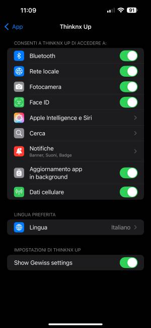
- Enable the Gewiss configuration in the Thinknx Up app
- Go to Settings → App → Thinknx Up → Show Gewiss settings
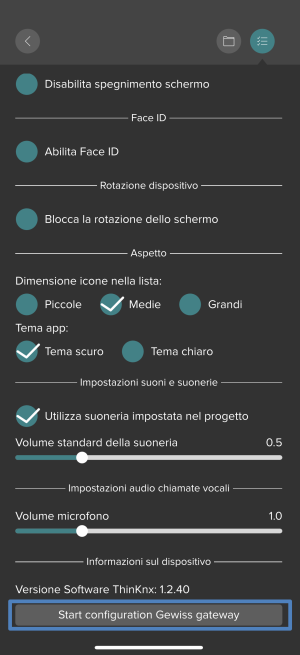
- Open the Thinknx Up app
- Go to the Settings menu
- Scroll to the bottom and select Start Gewiss System Configuration
- Press and hold the Home Gateway programming button for 4 seconds until the LED starts blinking
- Wait for the blinking to stop to complete the association
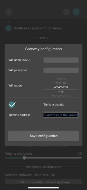
- Enter the Wi-Fi network name (SSID), respecting uppercase and lowercase
- Enter the Wi-Fi password
- Select the security type (e.g., WPA2-PSK2)
- Enable Thinknx if available
- Enter the Thinknx server IP address
Creating a Gewiss Smart Home system in Thinknx
Add the Gewiss Home Gateway object in the System menu.

Start the gateway configuration: click on the button with the three dots.

Click on the Add button.

Define the name: type in the Name field the name of your Smart Home system (e.g.: My Home). Click on the button with the three dots in the configuration field.

Click on the Configuration tab.

In the Plant field select the mac-address of the Home Gateway (select the mac-address of your Home Gateway from the list).
In the Mode field select:
- Local: when you want to create the ZigBee network configuration from scratch (network creation, bindings, etc.)
- Cloud: when you want to upload a ZigBee configuration already created using the Home Gateway app and migrated to Thinknx (you will be asked for the account to access the system)

Below are the steps to migrate a system configured with the Home Gateway app to Thinknx:
- From the Home Gateway app menu select Manage the Home
- Select Managing the gateway
- Select Configure the gateway
- Select ThinKnx parameters
- Click on Modifying the parameters
- Follow the instructions provided by the app

Click on the Request Configuration button.

At this point you can start configuring the ZigBee network (network creation, bindings definition, etc.), as described in the next chapter:
Configuration Tabs
Viewer The Viewer tab lists all ZigBee devices added to the project, the auxiliary input and the shift command.

Network The Network tab allows the creation of the ZigBee network during the first commissioning or the addition of ZigBee devices at a later stage (e.g. maintenance).
- Open ZigBee Network – opens the ZigBee network (Coordinator) and allows ZigBee devices to join; joined devices are listed in the right window
- Close ZigBee Network – closes the ZigBee network (Coordinator)
- List found devices – lists all devices joined to the network

- Add devices – adds to the project all checked devices from the right window; added devices are then listed in the left window

Special functions for ZigBee device management: The following functions are activated by left-clicking on a specific device:
- Identify – activates the device to identify it on the field
- Copy – copies to the clipboard the following device information: ID, IEEE code, Model
- Rename – renames the device
- Remove – removes the device from the project while keeping it joined to the ZigBee network
- Reset – factory reset; the device is also removed from the ZigBee network
- Help – opens the default web browser to the Gewiss website related to the selected ZigBee device

By clicking on the lens icon, the function Identify device from the field is activated.

When a ZigBee device is activated on the field (e.g. pressing the local button of a dimmer), the corresponding device in the left window is highlighted. The function stops when clicking again on the lens icon.

To exit this feature, simply tap the magnifying glass again, or it will close automatically after a period of inactivity.
Parameters This tab allows defining and modifying parameters of ZigBee devices included in the project. Parameter values define device behaviour.
In the left window all ZigBee devices are listed. In the central window the parameters of the selected device are shown.
- Fetch – loads parameters from the selected ZigBee device
- Save – saves modified parameters
In the right window, commands can be sent directly to the selected device.
Example Dimmer: for a Dimmer the following commands are available:
- On – switches the dimmer ON
- Off – switches the dimmer OFF
- DimTo – sets the illumination level (value between 0 and 1; 0.2 = 20%)


Example Shutter: for a Roller Shutter the following commands are available:
- GoToTiltPosition – sets the tilt angle of the slats when the shutter type is Blinds (value between 0 and 1; 0.2 = 20%)
- GoToLiftPosition – controls the lowering or raising of the roller shutter (value between 0 and 1; 0.2 = 20%)

For sensors (water sensor, door sensor, movement sensor, etc.) commands cannot be sent, but actuators can be defined directly in this tab for alarm ON and OFF conditions.
The window is split into two sections:
- Behaviour – defines sensor behaviour
- Linked channels – actuators commanded when alarm is ON or OFF
Example: If *behaviour when True = 0* and *behaviour when False = 1* are set, and the linked channel controls the water valve, the valve opens when a water leakage is detected and closes when the alarm ends.

Example for GW1X826: The activation of ‘automatic disconnection’, in the case of the GW1X826 actuator, is performed by setting the value to 65535; otherwise, the disconnection function is disabled.


Bindings Bindings allow ZigBee devices to directly exchange ZigBee commands. The “Check all” option can be used only when the selected target devices support the same commands The “Delete all” option can be used to remove all created bindings either for the selected source device or for all source devices
Example: to control a light using a ZigBee push button, a binding must be created between the push button and the actuator.
- Localize
- Identify the command by pressing the physical button
- The command name appears in the left window
- Compatible actuators are listed in the central window
- Select one or more actuators
- Select the command type
- Click Add to create the binding

After creation:
- The created binding is shown in the lower left window
- All bindings are listed in the right window (deletable only)
- Click Stop once all bindings are defined

Smart Plate This tab is used to configure Smart Plates.
To add a Smart Plate:
- Insert – identify the Smart Plate by typing its ID(reported on the plate)
- Localize – recommended method:
- Cover the proximity sensor for at least 5 seconds
- The Smart Plate is identified
- Click Stop

To configure the Smart Plate:
- Configure – opens the configuration window,that allows to configure all the function and parameters of the Smart Plate

- List – defines the composition of devices installed inside the Smart Plate
- Starting from the left of the Smart Plate devices must be selected among the ones that are listed in the left window

You can right-click a device and move it left or right to change its position.


- Localize – identifies connected devices by pressing local buttons
- Starting from the left of the Smart Plate it is enough to «push» (local push button) of each connected device included in the Smart Plate
- If there are «traditional» devices it must be specified
- The icons of the connected devices cannot be modified (because they depend on the function of the device)

- Shift – allows to define the commands associated to the Shift function of the Smart Plate:

- Click on each «device» (a device can have one or two push bitton, see the symbol [+]) to define the actuator to be commanded and the command to be given, in the example below it is defined to give a ON command to the Smart Plug, by mean the first push button on the left:


- To define the icons displayed when the Shift function is activated, click on each icon and then select the desired icon among the library proposed:

- Parameters – allows to define the behaviour of the Smart Plate: language, colour of the strip led, if in stand-by shall display the time or the temperature (for the temperature in the project there shall be at least one thermostat), etc

- Alarms setting – allows to define what are the alarms that has to be displayed on the Smart Plate, for each type of alarm a predefined message is displayed, the type of alarms are
- Flooding – when one of the water sensors detects a water-leakage
- Window – when one of the window sensors detects a window-opened
- Movement – when one of the movement sensors detetcts movement
- Smoke – when one of the smoke sensors detetcs smoke
- Connectivity – when one of the ZigBee device has problem of connectivity
Alarm messages can be displayed on all Smart Plates or only on selected ones.


Batteryless This tab allows defining commands sent by Batteryless push buttons.
- Add – adds a Batteryless push button
- In the lower left window is reported the «binding created»
- In the rigt-window are reported all the «bindings» created», it is possible to modify/delete each one

To configure a Batteryless push button:
- Insert the QR-Code associated to the Batteryless push-button
- Read by using your Smartphone the QR-Code attached on the back of the Batteryless push-button
- Report the Qr-Code on the field named «Qr-Code»
- Select if you want to configure it as a 4 or 2 push buttons

- Give a name to the batteryless push button
- Configure each single push-button (A0, A1, B0, B1) defining the actuator to be commanded (e.g. Light) and the command to be given (e.g.: Toggle)


Diagnostic This tab is mainly used for maintenance operations.
* Reset devices – factory reset of one or all devices
- Replace device – replacement of a faulty device

Associations for Thinknx Up and KNX
This section describes how to create associations between Thinknx objects and Gewiss Connected Smart Home objects.
Thinknx objects represent a logical link to Gewiss Smart Home devices and must be used whenever Smart Home data (commands, status, measures) are required inside Thinknx functions, such as:data logging, scenes, and logic functions.
To create the associations:
- Go to System
- Select Gewiss Home Gateway
- Select the desired Hub
The following sections allow the assignment of Gewiss smart home Devices to Thinknx and KNX group addresses.
Lights
This section allows defining Thinknx objects associated with Smart Home light devices.
- Click on the three dots at the end of the Lights line
- Select Add

Define the following parameters:
- Name – name of the Thinknx object
- Device – select the Smart Home light device
- KNX Gateway – enable to link the object to a KNX address
- Light type – On/Off, Dimmer, Any
- KNX command and feedback groups – KNX group addresses linked to the object

Thermostats
This section allows defining Thinknx objects associated with Smart Home thermostats.
- Click on the three dots at the end of the Thermostats line
- Select Add

Define the following parameters:
- Name – name of the Thinknx object
- Device – select the Smart Home thermostat
- KNX Gateway – enable to link the object to a KNX address
- KNX groups – KNX group addresses linked to the object

Shutters
This section allows defining Thinknx objects associated with Smart Home shutter devices.
- Click on the three dots at the end of the Shutters line
- Select Add

Define the following parameters:
- Name – name of the Thinknx object
- Device – select the Smart Home shutter
- KNX Gateway – enable to link the object to a KNX address
- KNX groups – KNX group addresses linked to the object

Analog values
This section allows defining Thinknx objects associated with Smart Home values (status, measures, alarms, etc.).
- Click on the three dots at the end of the Analog values line
- Select Add

Define the following parameters:
- Name – name of the Thinknx object
- Device – select the Smart Home device
- Reported property – select the value to be associated (status, measure, alarm)
- KNX Gateway – enable to link the object to a KNX address
- KNX value and feedback groups – KNX group addresses linked to the object

Object Assignment for Control
This section describes how to visualize and control Gewiss Smart Home objects in Thinknx supervision pages.
General steps:
- Add a Thinknx graphic object to the supervision page
- Associate the corresponding Thinknx object
- Configure object parameters
Control of an ON/OFF light
- Add Object Switch to the supervision page
- Configure the parameters:
- Switching type – ON/OFF normally open
- Bus type – Gewiss Smart Home
- Hub – select the Home Gateway
- Light – select the Thinknx light object

Control of a dimming light
- Add Object Switch to the supervision page
- Configure the parameters:
- Switching type – Dimmer
- Bus type – Gewiss Smart Home
- Hub – select the Home Gateway
- Light – select the Thinknx dimmer object

Control of a roller shutter
- Add Object Roller Shutter to the supervision page
- Configure the parameters:
- Bus type – Gewiss Smart Home
- Hub – select the Home Gateway
- Shutter – select the Thinknx shutter object

Control of a thermostat
- Add Object Thermo Comfort to the supervision page
- Configure the parameters:
- Bus type – Gewiss Smart Home
- Hub – select the Home Gateway
- Thermostat – select the Thinknx thermostat object

Visualization of a value
This allows visualization of measures, alarms, or status values.
- Add Object Analogue Value to the supervision page
- Configure the parameters:
- Data source – Gewiss Smart Home
- Hub – select the Home Gateway
- Analog – select the Thinknx analog object
Values can be analog (e.g. temperature) or binary (e.g. alarm).

Writing a parameter value
Writing a parameter value to a Gewiss Smart Home device. To write a parameter value:
- Add Object Generic Command to the supervision page
- Define the parameters associated with this object
- Command – select the Gewiss Smart Home device and then the value (e.g. parameter) to be written

When clicking on the Command property (see image above), the configurator helps in identifying the value to be written by using a simple navigation tree, which allows browsing all objects defined in the system.
Follow these steps:
- Select the Gewiss Home Gateway to which the desired device belongs
- Select the desired device (in the example, a thermostat)
- Select the parameter of the device to be written (in the example, the Set season parameter, which defines how the thermostat algorithm operates:
- Cool for cooling
- Heat for heating)
Using this approach, it is possible to define a generic command button (in a supervision page) to set the thermostat operating mode to cooling (summer) or heating (winter).

Commands between different Home Gateways
A Thinknx server can manage more than one Home Gateway. As for other protocols and systems managed by Thinknx, it is possible to use a command coming from a device connected to one Home Gateway (e.g. a push button) to control a device or an action belonging to a different Home Gateway.
For example: a connected push button (e.g. GWA1241) belonging to one Home Gateway can command:
- a connected actuator (e.g. GW10826),
- or trigger another action (e.g. display a message on a Smart Plate)
belonging to a different Home Gateway.
In the same way, a connected push button can command any actuator through other protocols (e.g. KNX, Modbus, etc.).
The object used for this purpose is the Thinknx Universal Gateway object.
The steps are:
- Define a Thinknx object associated with the desired push button of the Gewiss Smart Home (e.g. auxiliary command, connected push button, connected batteryless button)
- Define a Universal Gateway object activated by the connected command and configure, as its action, the desired actuation on a device belonging to a different Home Gateway
Example: command between two different Home Gateways
In this example, when a push button wired to an auxiliary input of a connected device is pressed, a message is displayed on a Smart Plate belonging to a different Home Gateway.
Step 1 – Define the Analog Value object
Define a Thinknx Analog Value object associated with the auxiliary input of the connected device to which the push button is wired.
Configure the following parameters:
- Name – name of the object
- Device – select the connected device and the auxiliary input used for the command (in this example: auxiliary input 1 of the device “Light”)
- Reported property – select the property that triggers the command (for this example, Generic is sufficient)
- KNX data type – define the data type using KNX data types (in this example the value is a command, so Boolean is suitable)
- KNX value group – not used in this example
- KNX value feedback – KNX group address associated with this command
Whenever the push button is pressed or released, a telegram is sent on this KNX address:
- value 1 when the button is pressed
- value 0 when the button is released
This KNX address will be used to trigger the Universal Gateway object defined in the next step.

Step 2 – Define the Universal Gateway object
Define the Universal Gateway object that activates the desired action on a device belonging to a different Home Gateway (in this example: displaying a message on a Smart Plate).
- Go to the System section
- Add a Universal Gateway object

A single Universal Gateway object can manage up to three independent actions. In this example, only one action is used: C1.

Step 3 – Configure the Universal Gateway parameters
Configure the Universal Gateway object as follows:
- Name – name of the Universal Gateway object
- KNX group – KNX group address on which the triggering telegram is received (in this example: 6/6/6, the same address used by the Analog Value object)
- Data type – define the data type using KNX data types (in this example: Boolean)
- C1 enabling – enable action C1
- C1 command – select the command/action to be executed (in this example: display the message “Buongiorno” scrolling from left to right on a Smart Plate, with the LED strip blinking green at 1 Hz)

Configure the activation condition:
- C1 condition – select Send if equal
- C1 value – set value to 1
With this configuration, the message is displayed on the Smart Plate when the value received from the KNX address 6/6/6 is 1, that is when the push button connected to the auxiliary input is pressed.
Command of a Gewiss Smart Home device in a Scene
A Thinknx Scene object can also manage commands and actions on Gewiss Smart Home devices. Within a Scene it is possible to include both:
- commands for connected devices (lights, shutters, actuators),
- and actions such as messages displayed on one or more Smart Plates.
The steps to define a Scene object are:
- Define a Thinknx Scene object at System level, defining the list of actions to be executed, including commands/actions for Gewiss Smart Home devices
- Define how the Scene is triggered (e.g. by an alarm from a connected device or by a button on a supervision page)
The following example describes a Scene that includes actions on:
- a roller shutter,
- a dimmer of the Gewiss Smart Home,
and is activated both by:
- a window alarm from Gewiss Smart Home,
- and a button on a supervision page.
Step 1 – Define the Scene object
Define the Thinknx Scene object.
- Go to the System section
- Add a Scene object

Configure the following parameters:
- Name – name of the Scene object
- KNX group – KNX group address used to trigger the Scene (the Scene can be triggered by any Thinknx function or by any device writing to this group)
- KNX data type – data type of the value written to the KNX group
- Trigger value – value written to the KNX group that triggers the Scene
- Record – if enabled, the user can add and modify actions autonomously (without system integrator intervention)
- Restartable – if enabled, the Scene can be retriggered before the previous execution has finished
- Hide configuration actions – if enabled, actions defined during configuration are not visible to the user
- Collection – list of actions executed by the Scene
For each action in the Collection, the configurator provides a simple navigation tree to identify the object to be commanded among all objects defined in the project.
For Gewiss Smart Home devices, select in the navigation tree:
- the Home Gateway to which the device belongs,
- the device,
- the action/command to be executed on the device.
In this example, the Scene includes:
- a command on a roller shutter: command of moving up
- a command on a light (ON/OFF or dimming): command to switch ON


Step 2 – Trigger the Scene from a window sensor
Define a Thinknx Analog Value object associated with the alarm detected by the window sensor.
Configure the following parameters:
- Name – name of the object
- Device – select the window sensor that triggers the Scene
- Reported property – select Contact switch (alarm condition)
- KNX data type – define the data type using KNX data types (in this example it is an alarm, so Boolean is suitable)
- KNX value group – not used in this example
- KNX value feedback – insert the KNX group address that triggers the Scene (in this example: 7/7/7, previously defined for the Scene)
When the window sensor detects an open window, the telegram sent on this KNX address triggers the Scene.

Step 3 – Trigger the Scene from a supervision page
Add a Scene Command object to the supervision page.
Configure the following parameters:
- Label – name of the Scene Command object shown on the supervision page
- Scene object – name of the Scene object (System object) to be triggered (in this example: Scenario, previously defined)
When the user presses the Scene Command button on the supervision page, the associated Scene is executed.

OTA Device Update
After deploying the project, locally or on the cloud, open the ThinKNX client.
Select whether to load the project locally or on the cloud using one of the options shown in the following image.

If the project is loaded on the cloud, enter the server serial number and the cloud password.
If the project is loaded locally, enter the Configurator URL, visible in the Configurator, preceded by http: (see the example in the figure where the URL is first shown in the Configurator and then how to enter it in the client).


Once the project is loaded, open it and click on the functions that were created in the Configurator.

Scroll down until you reach the settings section, where the three dots are displayed next to it, and click on them.

In the page that opens, click on the OTA manager and log in. All systems available on the server will be displayed. Select the system and the devices you want to update within the selected system.

N.B. If there are no devices available for update in the system, the message “No device found” will be displayed.
- gw_manager.txt
- Last modified: 2026/09/10 11:01
- by francesco


