Modbus

The Modbus protocol enables data exchange between automation devices over serial or Ethernet communication. Through the Gateway Modbus and Gateway Modbus Slave objects, the Thinknx server can read and write Modbus values, make them available to the supervision system, and exchange them with the KNX system.
This guide describes:
- the fundamental concepts required to interpret the Modbus documentation of a device;
- how to configure the Thinknx server as a Modbus Master;
- how to create and use Datapoints;
- bidirectional integration between Modbus and KNX;
- how to use the Thinknx server as a Modbus Slave;
- commissioning and troubleshooting procedures.
Fundamental concepts
Master and Slave
In Modbus communication, the Master initiates requests, while the Slave responds to the read or write operations it receives. A Slave does not initiate communication with the Master or with other Slaves.
When the Gateway Modbus object is used, the Thinknx server operates as a Master and polls one or more Slave devices. It can therefore read their data cyclically or send write commands.
When the Gateway Modbus Slave object is used, the Thinknx server exposes its Datapoints to an external Master, which can read or write them according to the configured settings.
In Modbus TCP implementations, the terms Client and Server are also used. From a communication perspective, the Client sends the request and the Server responds. In the terminology used by the Configurator, the Gateway Modbus Master normally acts as the Client, while the Slave device acts as the Server.
Modbus data areas
Modbus data is organised into four main areas.
| Data area | Size | Standard access | Read functions | Write functions |
|---|---|---|---|---|
| Coil | 1 bit | Read and write | 1 | 5 or 15 |
| Discrete Input | 1 bit | Read only | 2 | — |
| Input Register | 16 bits | Read only | 4 | — |
| Holding Register | 16 bits | Read and write | 3 | 6, 16 or 22 |
The data area is not determined only by the number shown in the device manual. The Modbus Function used determines whether the server must access, for example, a Coil or a Holding Register.
Modbus functions
The main functions available in the configuration are summarised in the following table.
| Function | Name | Use |
|---|---|---|
| 1 | Read Coils | Reads the status of one or more Coils. |
| 2 | Read Discrete Inputs | Reads one or more digital inputs. |
| 3 | Read Holding Registers | Reads one or more Holding Registers. |
| 4 | Read Input Registers | Reads one or more Input Registers. |
| 5 | Write Single Coil | Writes the status of a single Coil. |
| 6 | Write Single Holding Register | Writes a single Holding Register. |
| 15 | Write Multiple Coils | Writes multiple consecutive Coils. |
| 16 | Write Multiple Holding Registers | Writes multiple consecutive Holding Registers. |
| 22 | Mask Write Register | Modifies selected bits within a Holding Register. |
The function must be supported by the device and must correspond to the data area specified in its Modbus documentation.
Modbus addressing and Thinknx offset
Device manuals do not always use the same addressing system. Some number registers starting from 1, while others show the protocol address directly, starting from 0.
The Thinknx server automatically applies an offset of -1 to the address entered in the Configurator.
Transmitted address = Address entered in the Configurator - 1
| Address entered in the Configurator | Address transmitted by the server |
|---|---|
| 1 | 0 |
| 10 | 9 |
| 100 | 99 |
If the manual numbers registers starting from 1, the corresponding number can normally be entered directly in the Configurator. The server will then automatically apply the offset.
If the manual already shows the protocol address starting from 0, enter the value increased by 1 in the Configurator. For example, to transmit protocol address 0, address 1 must be configured.
The traditional notations 00001, 10001, 30001, and 40001 also identify the data area:
| Traditional notation | Data area | First protocol address |
|---|---|---|
| 00001 | Coil | 0 |
| 10001 | Discrete Input | 0 |
| 30001 | Input Register | 0 |
| 40001 | Holding Register | 0 |
For example, notation 40001 normally identifies the first Holding Register. In the Thinknx Datapoint, select the Function associated with Holding Registers and configure the numeric address required by the Configurator, without automatically entering the complete value 40001.
A typical configuration in this case is:
| Information in the manual | Data Address in the Configurator | Transmitted address |
|---|---|---|
| Holding Register 40001 | 1 | 0 |
Warning: before configuring all Datapoints, always verify the convention used by the manufacturer by reading a single known value. Manually applying an additional -1 when the server already applies it results in the previous register being read.
Converting hexadecimal addresses
Some Modbus manuals show Datapoint addresses in hexadecimal format, normally identified by the 0x prefix. Before entering an address in the Configurator, convert it to the corresponding decimal value.
The conversion can be performed, for example, using the Windows Calculator in Programmer mode:
- open Calculator and select Programmer mode;
- select HEX;
- enter the hexadecimal address without the
0xprefix; - read the corresponding value shown under DEC.
For example:
0x0010 = 16
Converting from hexadecimal to decimal does not change the Thinknx offset rule. If 0x0010 already represents the protocol address, its decimal value is 16 and 17 must be entered in the Configurator so that the server transmits address 16.
| Information in the manual | Decimal value | Data Address in the Configurator | Address transmitted by the server |
|---|---|---|---|
| 0x0010 | 16 | 17 | 16 (0x0010) |
Warning: hexadecimal notation only indicates the numeric base. It does not indicate whether the manufacturer uses zero-based or one-based numbering. Verify this information in the device manual or by performing a test read.
Required information
Before configuring the Gateway Modbus, obtain the device manual or Modbus table and identify:
- the role of the device;
- communication mode: Modbus Serial, Modbus Serial on TCP, or Modbus TCP;
- Slave Address or Unit ID;
- Baud Rate, Data Length, Parity, and Stop Bits for serial communication;
- IP address and port for Ethernet communication;
- the address of each data item;
- the data area and supported Function;
- value type and size;
- register or byte order, if applicable;
- scaling factor, if applicable;
- accepted write-value range.
Also verify that the required communication port and, when applicable to the server model, the relevant Modbus licence are available on the server.
It is advisable to verify this information using an external Modbus program before configuring the complete integration in Thinknx.
Gateway Modbus – Thinknx server as Master
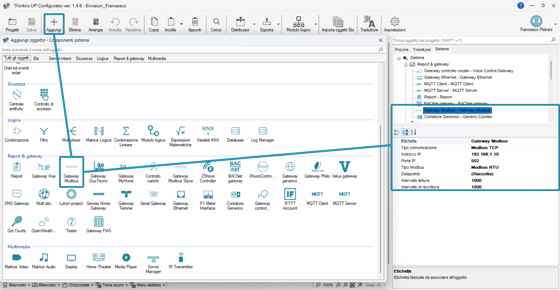
The Gateway Modbus object allows the Thinknx server to operate as a Modbus Master. The server cyclically polls the configured devices and can write values through Datapoints, the KNX gateway, or object commands.
To add the gateway, open the System section of the project, right-click the main node, and add the Gateway Modbus object from the gateway category.
Communication types
The Communication Type property defines the method used by the server.
Modbus Serial
This mode is used to connect the server directly to a serial bus, normally via RS485.
- Port Number: serial port used by the server for communication. The number depends on the server model.
- Modbus Type: Modbus variant used, for example Modbus RTU.
- Baud Rate: communication speed, which must match the device configuration.
- Data Length: number of bits used for data.
- Parity: parity-checking mode.
- Stop Bits: number of stop bits.
- Comm. Timings: timings used to optimise communication on the serial bus. These may depend on the adapter and the response times of the Slaves.
All devices on the same serial bus must use compatible communication parameters and must have a unique Slave address.
Modbus Serial on TCP
This mode is used when the serial bus is reached through an Ethernet-to-serial converter. The converter transports serial communication over the network without converting it into native Modbus TCP communication.
- IP Address: IP address of the serial converter.
- IP Port: TCP port on which the converter accepts the connection.
The port must match the one configured in the converter. It does not necessarily have to be the standard port 502.
Modbus TCP
This mode is used to communicate directly with a Modbus TCP device.
- IP Address: IP address of the Modbus TCP device.
- IP Port: port used by the device. The standard Modbus TCP port is 502, but the device may be configured differently.
Modbus Serial on TCP and Modbus TCP are not equivalent. Select the mode according to the protocol actually supported by the device or converter.
General parameters
- Datapoints: collection of data points read or written by the gateway.
- Poll Interval: delay, in milliseconds, between two consecutive polling sequences.
- Write Refresh Interval: interval between two rewrite sequences. It is used only by Datapoints for which Force Rewrite is enabled.
A very short Poll Interval increases traffic and may cause timeouts or instability, especially on serial buses with many devices. Start with a small number of Datapoints and a conservative interval, then reduce it only after verifying communication stability.
Configuring Master Datapoints
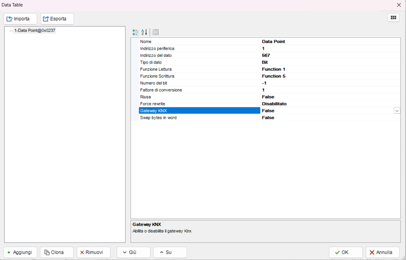
Open the Datapoints collection, add a new item, and configure the required parameters.

Identification and address
- Name: name used to identify the Datapoint in the project.
- Slave Address: address of the Slave device containing the data.
- Data Address: address of the data. The server transmits the configured value after automatically applying the -1 offset.
Use descriptive names, such as Supply temperature, Pump alarm, or Zone 1 setpoint, so that Datapoints can be easily identified when selected by other objects.
Data type and functions
- Data Type: type of data to be read or written. It must match the size and representation specified by the manufacturer.
- Read Function: Modbus Function used to read the value.
- Write Function: Modbus Function used to write the value.
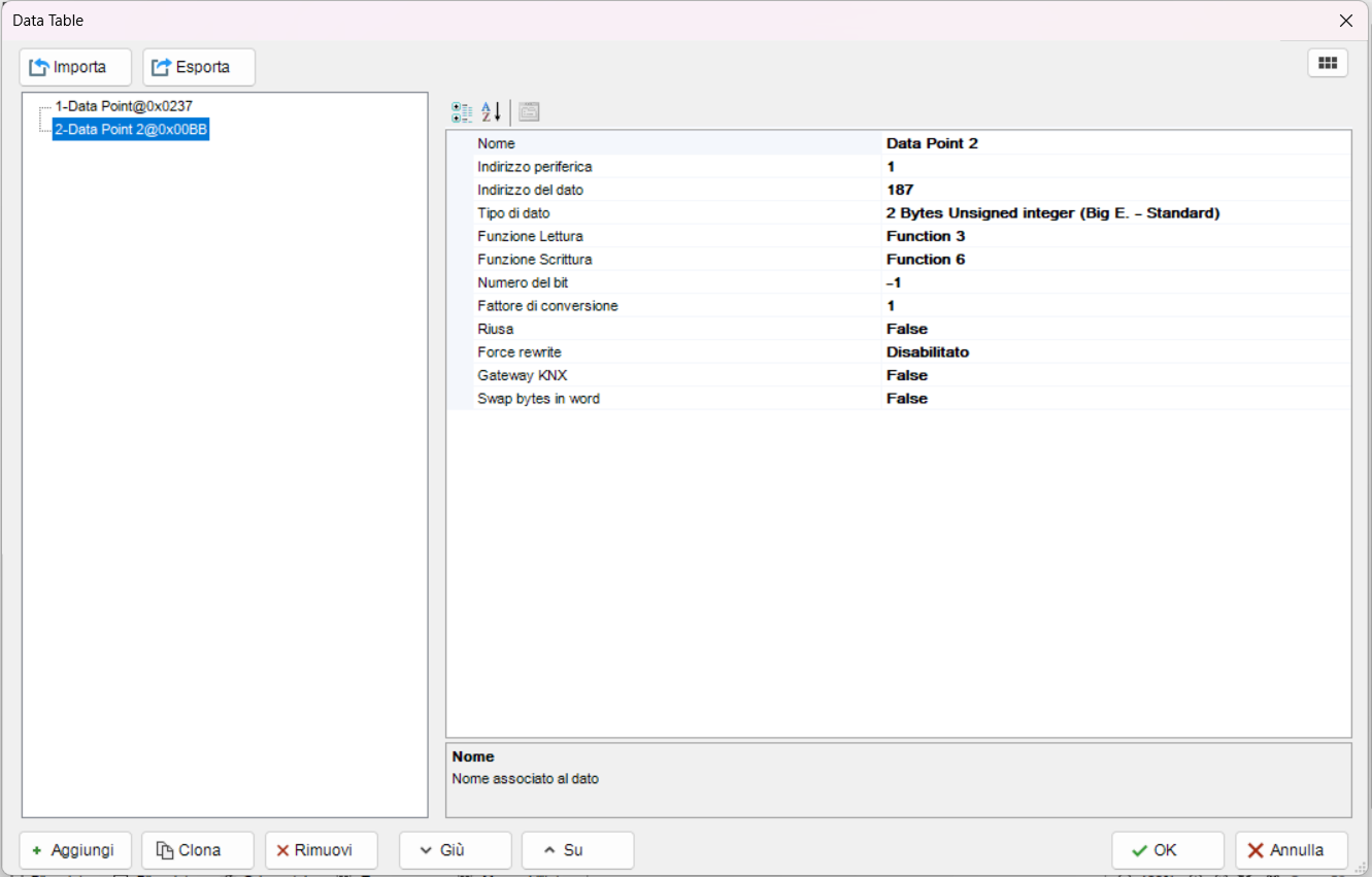
For example, an Input Register is normally read using Function 4 and cannot be written. A Holding Register is normally read using Function 3 and can be written using a function supported by the device, such as Function 6 or Function 16.
Value extraction and conversion
- Bit Number: identifies the bit used by the Datapoint when the required value is contained within a register.
- Conversion Factor: factor by which the raw value is multiplied.
For example, if the device returns 235 to represent 23.5 °C, use a conversion factor of 0.1.
Before applying the conversion factor, verify that the raw value and its sign are interpreted correctly. An incorrect data type may produce apparently random values or values far outside the expected range.
Reuse
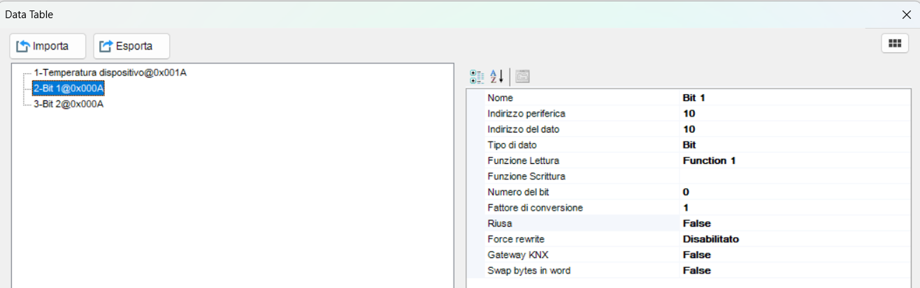
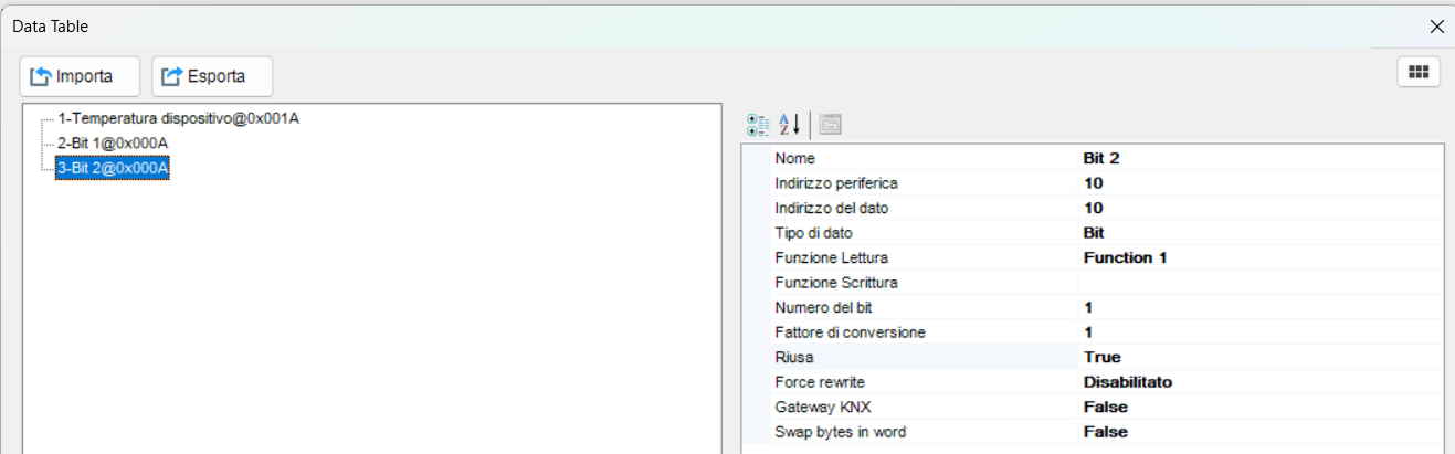
The Reuse property allows a completed read operation to be reused when multiple Datapoints extract different bits from the same address.
For example, if a Holding Register contains sixteen digital states, create multiple Datapoints with the same Slave Address and Data Address, changing only the Bit Number:
- disable Reuse on the first Datapoint;
- enable Reuse on the subsequent Datapoints.
The driver reads the register only once and uses the received value to extract the different bits. This reduces the number of requests sent to the Slave and improves polling speed.
Force Rewrite
When Force Rewrite is enabled, the server cyclically rewrites the last value sent to the Datapoint. The frequency is defined by the general Write Refresh Interval property of the Gateway Modbus.
Use this function only when the device requires periodic command refreshing. Do not enable it indiscriminately, as it increases traffic and the number of write operations.
KNX Gateway
By enabling KNX Gateway, the Datapoint can exchange its value with the KNX bus.
- KNX Data Type: KNX data type associated with the Modbus value.
- KNX Group from Modbus: group address to which the value read from Modbus is sent.
- Send if Change: sends the value to the KNX bus only when the Modbus value changes.
- Enable KNX to Modbus: enables communication from KNX to Modbus.
- Different KNX group: group address from which the server receives the value to be written to Modbus.
The standard data flow is:
Modbus device → Gateway Modbus → KNX feedback group
Enabling bidirectional communication adds the opposite flow:
KNX command group → Gateway Modbus → Modbus device
Verify that the KNX Data Type is compatible with the Modbus value and any Conversion Factor applied.
Gateway Modbus commands
The object commands allow Modbus write operations to be triggered from scenes, logics, buttons, or other Thinknx objects.
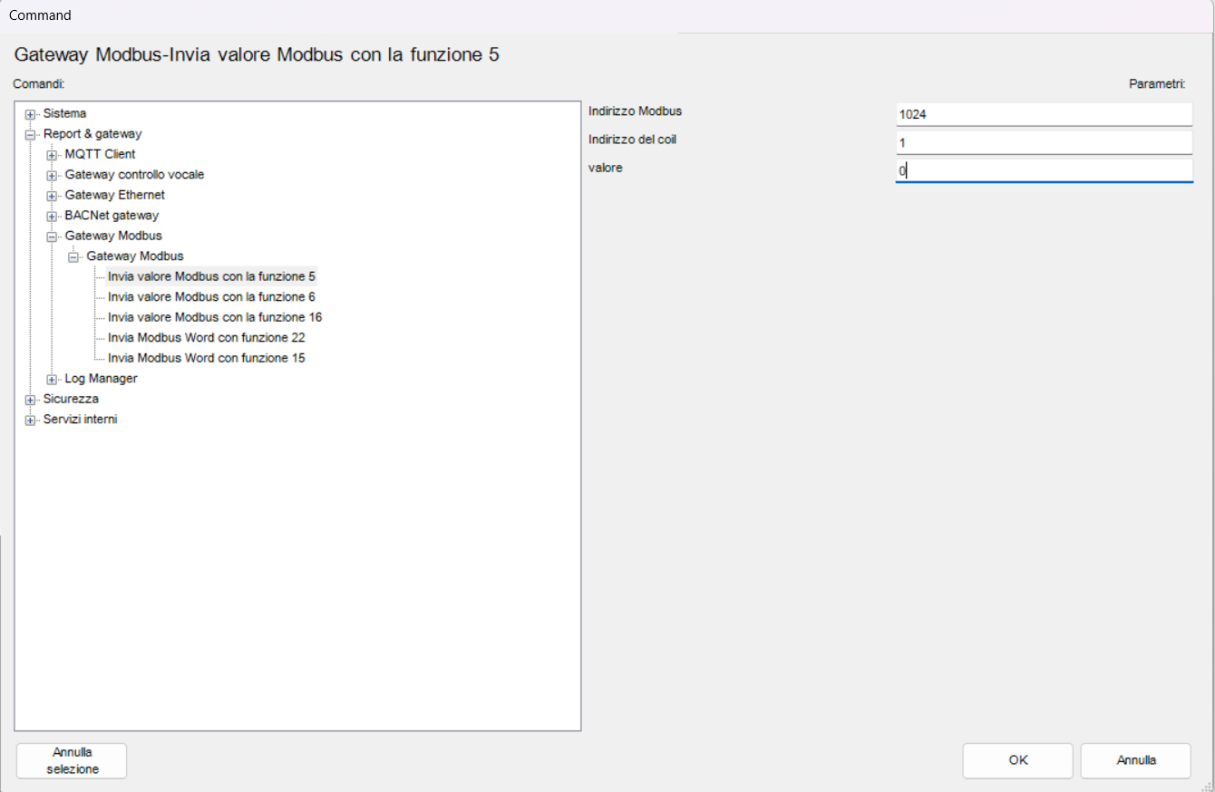
Function 5 – Write Single Coil
Writes the status of a single Coil.
In the Configurator, the command is named Send Modbus value with function 5 and uses the following parameters:
- Modbus Address: address of the Slave.
- Coil Address: address of the Coil.
- Value: value to write, 0 = OFF or 1 = ON.
The device must support Function 5 at the selected address.
Function 6 – Write Single Holding Register
Writes a single Holding Register.
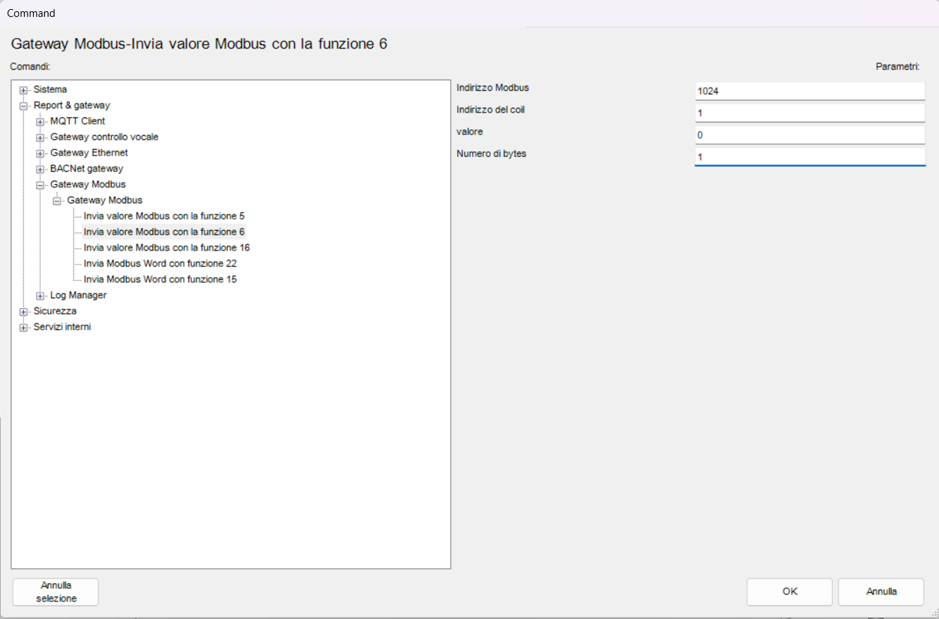
In the Configurator, the command is named Send Modbus value with function 6 and uses the following parameters:
- Modbus Address: address of the Slave.
- Coil Address: address of the register to write.
- Value: value to write.
- N.Byte: number of bytes configured for the value.
At Modbus protocol level, Function 6 operates on a single 16-bit register. Although the parameter is named Coil Address in the Configurator, for this function it identifies the address of the Holding Register to be written. Check the device manual for the accepted value format and range.
Function 15 – Write Multiple Coils
Function 15, also known as Write Multiple Coils, writes the status of multiple consecutive Modbus Coils simultaneously.
Warning: to trigger Function 15 from the supervision interface, use a Generic Command associated with the Send Modbus Word with function 15 command. Do not use a Light object, because Function 15 requires all the parameters needed to write multiple consecutive Coils and does not handle a simple ON/OFF command for a single Coil.
Each Coil represents one bit:
- 0 = OFF
- 1 = ON
The Coils are written starting from the address specified in First Register Address. The software uses a single decimal value to define the Coil states and internally converts it to binary. The least significant bit corresponds to the first Coil, the next bit to the second Coil, and so on.
To set the first 10 Coils to ON:
1111111111 = 1023
To set the first 20 Coils to ON:
11111111111111111111 = 1048575
In general, to set the first N consecutive Coils to ON:
Value = 2ᴺ - 1
| Number of Coils | Decimal value |
|---|---|
| 8 | 255 |
| 10 | 1023 |
| 16 | 65535 |
| 20 | 1048575 |
Individual Coils can also be controlled by setting only the corresponding bits. For example:
00000101 = 5
Value 5 sets the first and third Coils to ON, leaving all other Coils OFF.
Command parameters:
- Modbus Address: address of the Slave.
- First Register Address: address of the first Coil to write.
- Value: decimal value representing the Coil states.
- Number of coils: number of consecutive Coils to write.

Function 16 – Write Multiple Holding Registers
Writes one or more consecutive Holding Registers.
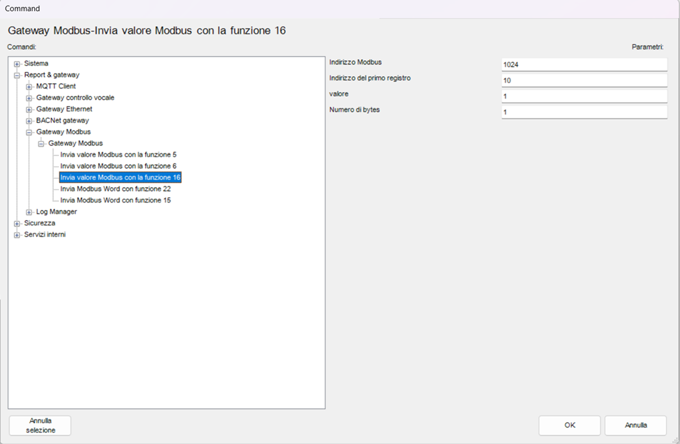
In the Configurator, the command is named Send Modbus value with function 16 and uses the following parameters:
- Modbus Address: address of the Slave.
- First Register Address: address of the first register.
- Value: value to write.
- N.Byte: number of bytes used by the command.
The configured size must be consistent with the number of registers and the value type required by the device.

Function 22 – Mask Write Register
Function 22 modifies selected bits within a Holding Register without treating the register as a simple complete write command.
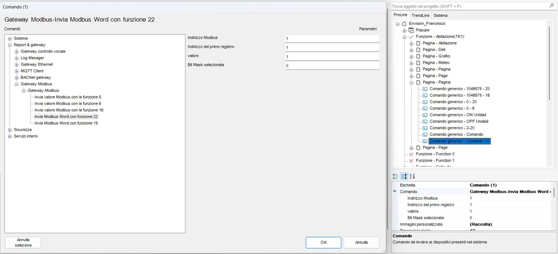
In the Configurator, the command is named Send Modbus Word with function 22 and uses the following parameters:
- Modbus Address: address of the Slave.
- First Register Address: address of the register.
- Value: value to apply.
- Selected Bits Mask: mask identifying the bits to be modified.
Initially verify the meaning of the mask and the expected result on a test register or using a Modbus simulator.
Master configuration examples
The following examples use demonstration values. Before applying them to a real device, replace all parameters with those specified in the relevant Modbus manual.
Example 1: reading a serial Holding Register
The objective is to read a temperature from a device with the following characteristics:
- Modbus RTU;
- Slave Address 1;
- 9600 baud, 8 data bits, no parity, and 1 stop bit;
- temperature available in the first Holding Register;
- Function 3;
- unsigned 16-bit value;
- raw value 235 corresponding to 23.5 °C.
Gateway configuration:
| Property | Value |
|---|---|
| Communication Type | Modbus Serial |
| Port Number | Serial port used by the server |
| Baud Rate | 9600 |
| Data Length | 8 |
| Parity | None |
| Stop Bits | 1 |
Datapoint configuration:
| Property | Value |
|---|---|
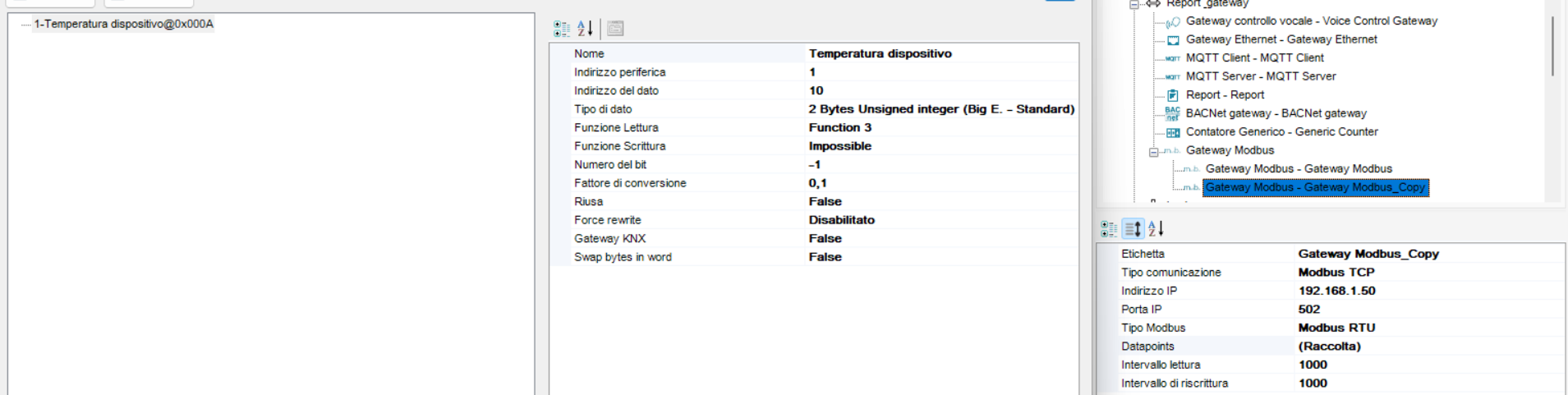
| Name | Device temperature |
| Slave Address | 1 |
| Data Address | 10 |
| Address transmitted by the server | 0 |
| Data Type | Corresponding unsigned 16-bit type |
| Read Function | Function 3 |
| Conversion Factor | 0.1 |
The expected value in Thinknx is 23.5.
Example 2: manual using zero-based protocol addresses
The manual explicitly specifies Protocol Address 25. Since this is already the address transmitted on the protocol, enter 26 in the Configurator.
| Item | Address |
|---|---|
| Address specified in the manual | 25 |
| Data Address in the Configurator | 26 |
| Address transmitted by the server | 25 |

Example 3: reading multiple states from the same register
A Holding Register contains several alarm states, one for each bit.
Create multiple Datapoints with the same Slave Address, Data Address, Data Type, and Read Function values. Configure a different Bit Number for each alarm.
Disable Reuse on the first Datapoint. Enable Reuse on the subsequent Datapoints so that the server reads the register only once and reuses the received value.
Example 4: Modbus–KNX integration
To send a temperature read from Modbus to the KNX bus:
- Configure and verify the Modbus Datapoint first.
- Enable KNX Gateway.
- Select the KNX Data Type corresponding to the temperature.
- Configure KNX Group from Modbus with the feedback group.
- Enable Send if Change if the value should be sent only when it changes.
To also allow writing from KNX to Modbus:
- Verify that the register is writable and that the Write Function is correct.
- Enable Enable KNX to Modbus.
- Configure Different KNX group with the command group.
- Send a test value and verify the response from the device.

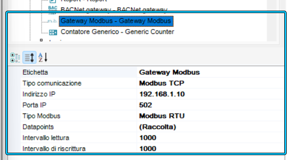
Example 5: reading via Modbus TCP
The objective is to read Holding Register 10 from a Modbus TCP device with IP address 192.168.1.50, port 502, and Unit ID 1.
Gateway configuration:
| Property | Value |
|---|---|
| Communication Type | Modbus TCP |
| IP Address | 192.168.1.50 |
| IP Port | 502 |
Datapoint configuration:
| Property | Value |
|---|---|
| Slave Address | 1 |
| Data Address | 10 |
| Address transmitted by the server | 9 |
| Read Function | Function 3 |
After uploading the project, verify that the server opens the TCP connection and receives a valid response from the device before adding other Datapoints.
Gateway Modbus Slave
The Gateway Modbus Slave object allows the Thinknx server to expose Datapoints to an external Master. The Master can read or write the available values according to the configured functions and addresses.

Communication parameters
The Communication Type property defines the communication method.
For Modbus Serial, the following properties are available:
- Port Number;
- Baud Rate;
- Data Length;
- Parity;
- Stop Bits;
- Custom Timing, used to modify the timings related to RTS management and serial transmission;
- Schedule Management, used to enable or disable schedule management.
For Modbus Serial on TCP or Modbus TCP, the IP Port property defines the port on which Gateway Modbus Slave listens. A remote IP address is not required because the Thinknx server operates as a Slave and waits for the Master to connect.
Additional properties:
- Device Address: address used to identify the server on the Modbus bus.
- Modbus Type: serial variant in use, selectable between RTU and ASCII.
- Datapoints: collection of values exposed by the server.
Slave Datapoint
The following properties are available for each Datapoint:
- Name: Datapoint name.
- Data Address (start): first address in the range where the data is exposed.
- Data Address (end): last address in the range where the data is exposed.
- Data Type: type of data read or written.
- Read Function: function used by the Master to read the value.
- Write Function: function used by the Master to write the value.
- Bit Number: bit of the value associated with the Datapoint.
- Conversion Factor: factor applied to the raw value.
- KNX Group: associated KNX group address.
- KNX Data Type: KNX data type.
- Send if Change: sends the value to the KNX bus when the Modbus value changes.
Usage example
To make a temperature available from the KNX bus to an external system:
- Add Gateway Modbus Slave.
- Configure the communication and the Device Address.
- Create a Datapoint with the required address, function, and data type.
- Associate the KNX Group containing the temperature value.
- Upload the project to the server.
- Use an external Modbus Master to read the configured address.
- Compare the received value with the value on the KNX bus.
Commissioning and verification
Initially, perform the verification using only one device and one Datapoint. After confirming that communication is working, add the remaining values.
Testing the device with Modbus Poll
Modbus Poll can be used as an external Master to test a Slave device independently of Thinknx.
Recommended procedure:
- Connect the PC to the device through the network or a serial adapter.
- Configure the parameters specified in the device manual.
- Set the Slave Address, Function, address, and register quantity.
- Read a single known value.
- Check both the address specified in the manual and whether it uses zero-based or one-based addressing.
- Record the working configuration and reproduce it in Gateway Modbus Thinknx.
If Modbus Poll cannot communicate with the device, resolve the issue before proceeding with the Thinknx configuration.
Testing the server with Modbus Slave
Modbus Slave can be used to simulate the device and observe the requests sent by the Thinknx server when it operates as a Master.
This test makes it possible to check:
- server connection;
- Slave Address;
- Function used;
- address transmitted after applying the -1 offset;
- number of registers or Coils;
- value sent in a write request.
For a Modbus TCP test, configure Gateway Modbus with the IP address of the PC running the simulator. Verify that the firewall and TCP port allow the connection.
Modbus Poll and Modbus Slave are available from the Modbus Tools website.
Analysing Modbus TCP with Wireshark
Wireshark can capture Modbus TCP traffic and analyse the requests and responses exchanged over the network.
Useful filters:
mbtcp
modbus
tcp.port == 502
ip.addr == 192.168.1.100
Replace the example IP address with the address of the device. The capture can be used to check the TCP connection, Function Code, addresses, requested quantities, data, and any error responses.
Wireshark cannot directly capture a Modbus RTU bus through a standard network interface. Serial traffic requires an interface and capture method suitable for the bus in use.
Troubleshooting
The device does not respond
Check:
- power supply and physical connections;
- polarity and wiring of the RS485 bus;
- selected serial port;
- IP address and TCP port;
- Slave Address or Unit ID;
- Baud Rate, Data Length, Parity, and Stop Bits;
- Modbus RTU, ASCII, Modbus Serial on TCP, or Modbus TCP mode;
- firewall and network connectivity;
- device response times.
Before modifying the Thinknx project, test the device with Modbus Poll or an equivalent tool.
The wrong register is read
- Check whether the manual uses zero-based or one-based addresses.
- Remember that the Thinknx server transmits the configured address minus 1.
- Verify that a second offset has not been applied manually.
- Do not automatically use the entire 40001 notation as the Data Address.
- Verify that the Read Function matches the data area.
The value is incorrect
- Verify the Data Type and value size.
- Check whether the value is signed or unsigned.
- Check any register or byte order specified by the manufacturer.
- Temporarily disable the Conversion Factor and check the raw value.
- Check whether the value occupies multiple consecutive registers.
- Verify the Bit Number when extracting a single bit.
Reading works but writing does not
- Verify that the data is writable.
- Check that the Write Function is supported by the device.
- Verify the accepted value range.
- Check the address and offset.
- Verify that Enable KNX to Modbus is enabled when the command comes from KNX.
- Test the write operation directly with Modbus Poll.
- Check for a Modbus Exception response.
Communication is unstable
- Increase the Poll Interval.
- Temporarily reduce the number of Datapoints.
- Use Reuse for multiple bits from the same register.
- Check the Write Refresh Interval and Force Rewrite settings.
- Check the wiring, termination, and quality of the serial converter.
- Verify that the Slave responds within the required time.
The Modbus value is not sent to KNX
- First verify that the Modbus Datapoint is read correctly.
- Check that KNX Gateway is enabled.
- Verify the KNX Data Type and group address.
- Temporarily disable Send if Change to rule out the possibility that the value is not being sent because it has not changed.
- Check the KNX monitor and the flags of the objects involved.
Modbus Exception
The most common exception responses are:
| Code | Meaning | Main check |
|---|---|---|
| 01 | Illegal Function | The function is not supported by the device. |
| 02 | Illegal Data Address | The requested address or range is not available. |
| 03 | Illegal Data Value | The requested value or quantity is not valid. |
| 04 | Server Device Failure | The device could not complete the operation. |
Always refer to the device manual, as the manufacturer may define additional conditions.
Quick diagnostic procedure
- Gather all parameters from the Modbus manual.
- Test the device with Modbus Poll or an equivalent tool.
- Read a single known value.
- Identify the addressing convention.
- Create only one Datapoint in Gateway Modbus Thinknx.
- Verify the transmitted address, taking the -1 offset into account.
- Check the raw value without conversions.
- Then verify the Data Type and Conversion Factor.
- Test writing, if required.
- Add the KNX gateway only after verifying Modbus communication.
- Gradually extend the configuration to the other Datapoints.